Configuring High Availability on Fortinet FortiGate Firewall based on FGSP
This topic provides an overview of the provisioning process and describes deployment considerations for Fortinet FortiGate High Availability (HA) using FortiGate Session Life Support Protocol (FGSP) with route based redundancy.
For more information about Fortinet FortiGate, see FortiGate / FortiOS documentation.
HA overview
When deploying Fortinet FortiGate firewalls on-premises, in a data center, or on Megaport Virtual Edge (MVE), using FGSP is a common approach for providing session redundancy. FGSP ensures that active sessions are synchronized between FortiGate peers, minimizing traffic disruption in the event of a firewall or link failure.
Historically, achieving HA-like session continuity in cloud or virtualized environments has been challenging, because it requires direct network paths between firewall peers and reliable session synchronization mechanisms. Megaport’s support for FortiGate firewalls on MVE and multi-vNIC functionality enables FGSP deployment, making session continuity possible even across virtualized network cores and multicloud connectivity.
FortiGate firewalls deployed on MVE can be configured with FGSP, combining the benefits of on-demand, as-a-service deployment, direct private connectivity to clouds and data centers, session synchronization, and orchestrated failover.
FGSP modes
Fortinet FGSP differs from the traditional Fortinet HA protocol, FortiGate Clustering Protocol (FGCP), in that it focuses on session synchronization, rather than providing a unified, cluster-based active-active load balancing mechanism. While FGCP has Active/Active and Active/Passive modes, FGSP is typically used with:
-
Two or more active FortiGate peers, where all devices can receive traffic as determined by the network layer. For example, router, SD-WAN, or an external load balancer.
-
Session synchronization across peers, ensuring that if a peer fails, active sessions continue on surviving devices. FGSP does not natively perform traffic failover. The upstream network, such as the router, SD-WAN overlay, or load balancer, must detect failures and redirect traffic to the surviving FortiGate instance.
FGSP operation
FGSP synchronizes active sessions between FortiGate peers over a dedicated vNIC or VXC. Each FortiGate maintains its own interfaces, while the upstream network, for example, router or load balancer, determines traffic distribution.
In the event of a failure, such as a FortiGate node going down or a network path failing, the surviving FortiGate takes over the active sessions. The network must route new flows to the surviving peer. FGSP ensures that the existing session states are preserved, so traffic continuity is maintained.
FGSP is particularly useful in virtualized or multicloud deployments, where firewalls are deployed as active gateways in an overlay SD-WAN, and high availability cannot rely solely on traditional physical HA links.
Architecture overview
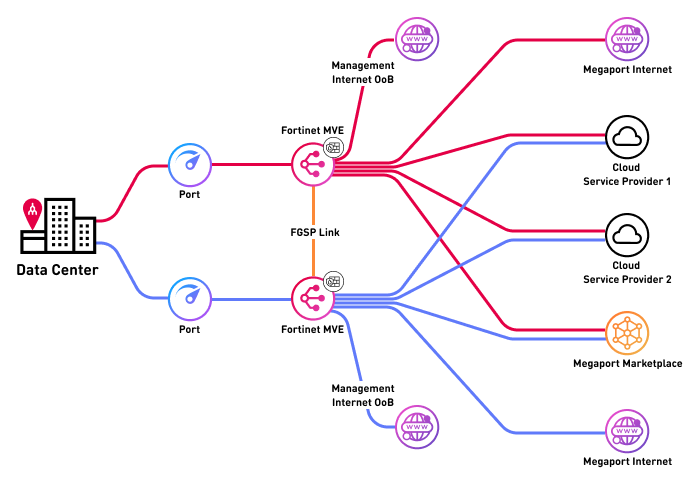
The architecture deployed in this topic shows FortiGate firewalls on MVE with FGSP session synchronization. There are two MVEs running FortiGate OS, each with its management interface connected to the internet. A dedicated VXC is created between the two MVEs to carry FGSP session synchronization traffic, while the data plane VXCs connect to one or more cloud environments or other networks.
Note
In a production deployment, there might be additional VXCs for connecting to other networks, internet links, or VPNs. Management interfaces can also reside on private networks instead of the public internet, depending on your design.
The image below shows a high-level architecture diagram of the Fortinet FGSP deployment on MVE, showing session synchronization between two FortiGate peers and connectivity to multiple cloud environments, the internet, and Megaport Marketplace.
Interface details
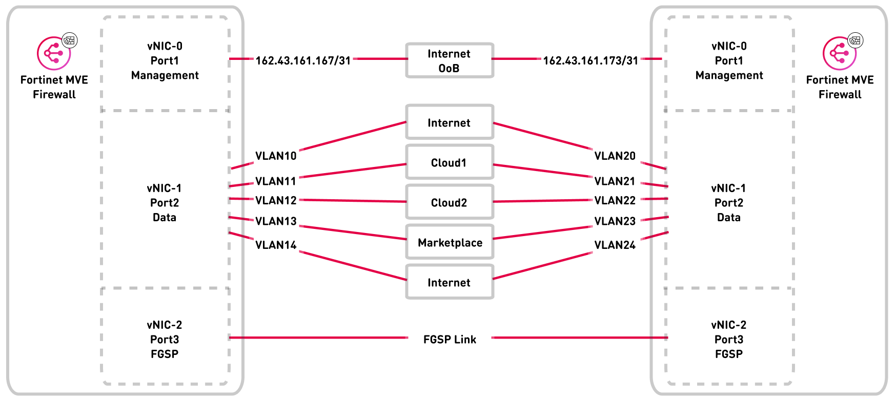
The following diagram shows the interface mapping for the FortiGate FGSP deployment. It shows vNIC 0 for management, vNIC 1 for data plane, and vNIC 2 for FGSP session synchronization, and data plane VXCs connect to cloud or overlay networks.
Deploying FGSP on MVE
Deploying FGSP on an MVE requires the following configuration steps in the Megaport Portal and FortiGate OS:
-
Deploy the first FortiGate MVE instance
-
Deploy the second FortiGate MVE instance
-
Configure FGSP in FortiGate OS
Deployment considerations
Each step of deploying a FortiGate MVE with FGSP requires some special considerations.
Deploy the first FortiGate MVE instance
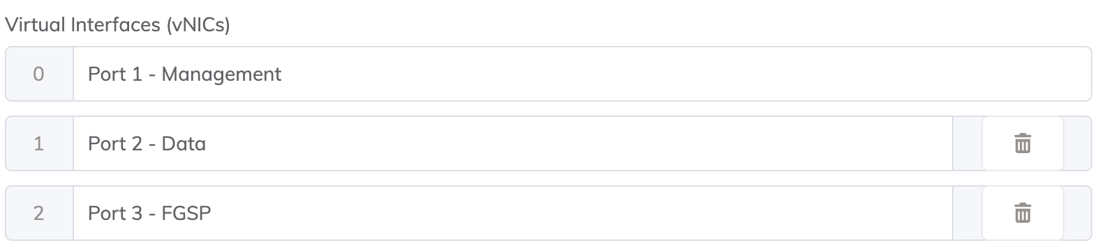
We recommend that you assign a dedicated vNIC for FGSP session synchronization between peers. We also recommend that you assign a vNIC for management and a vNIC for data plane interfaces. A typical deployment requires three interfaces: management, data, and FGSP sync, but you can deploy up to 5 vNICs if required.
Note
Fortinet recommends that FGSP session synchronization traffic is carried over a dedicated network segment or interface that is not shared with management or data traffic. This ensures reliable session synchronization, minimizes congestion, and avoids issues caused by NATNetwork Address Translation (NAT) translates private, unregistered IP addresses used within an organization’s internal network into a single registered public IP address before sending packets to an external network. NAT enables private IP networks to access the internet and cloud services.
or filtering on shared links. For more information, see the Fortinet FGSP documentation.
Deploy the second FortiGate MVE instance
Create a second FortiGate MVE of the same model and firmware version in the same or different metro. For performance-sensitive deployments, we recommend that the network path between the two MVE instances has low latency, but sub-millisecond latency is not required. Both FortiGate instances must be identical in model and firmware to support FGSP.
Create VXCs for FGSP traffic
If vNIC 0 is for management, vNIC 1 for data plane, then vNIC 2 can be assigned for FGSP session synchronization. Create a VXC between vNIC 2 on each MVE. Both ends should be untagged (no VLAN). This link will carry FGSP session synchronization traffic.
Note
Ensure the FGSP VXC has sufficient bandwidth to handle peak session table synchronization traffic. Typical deployments start at 1 Gbps, but adjust based on the expected number of active sessions.
Configure FGSP in FortiGate OS
Configure each FortiGate MVE as an FGSP peer using the appropriate peer IP address over the VXC. Enable session pickup options to synchronize TCP, UDP, ICMP, NAT, and expectation sessions as required. Verify connectivity between peers and ensure session tables are being synchronized correctly. For more information, see the FortiGate FGSP basic peer setup documentation.
Creating the FortiGate MVEs in the Megaport Portal
The first step is to create and deploy two FortiGate MVEs in the Megaport Portal. Unlike traditional HA clustering (FGCP), Fortinet FGSP does not require multiple dedicated HA interfaces. Instead, it requires a reliable network path for session synchronization between FortiGate peers.
A typical FortiGate FGSP deployment on MVE includes:
-
A management interface
-
A data plane interface
-
A recommended dedicated interface (or VNIC) for FGSP session synchronization.
To create and deploy FortiGate MVEs
- In the Megaport Portal, go to the Services page.
-
Create a Fortinet FortiGate MVE as described in Creating an MVE Integrated with Fortinet.
-
On the MVE Details page, configure the required Virtual Interfaces (vNICs):
Repeat the same process to create a second FortiGate MVE, ensuring:
-
The same FortiGate model
-
The same FortiOS version
-
Deployment in a suitable metro based on your latency and design requirements
-
A Megaport Internet connection is created for the management interface of each FortiGate MVE.
This allows initial access to the FortiGate GUI and CLI for configuration and validation. This is the most common approach during initial deployment. However, the management interface can instead be connected to a private VXC once an alternative management path (such as a bastion host, Virtual Private Network (VPN), or private management network) is in place.Note
Ensure that management access is secured using appropriate firewall policies, trusted source IPs, and authentication mechanisms.
There will now be two MVEs deployed.
Creating a VXC for FGSP session synchronization
Now that the FortiGate MVEs have been created, the next step is to create a private VXC for FGSP session synchronization between the two devices.
Unlike traditional HA implementations, Fortinet FGSP requires a single reliable network path between peers to synchronize session state. This path must be direct, routable, and free of NAT.
Use the dedicated FGSP interface on each MVE (vNIC 2 in this example) and connect it to the same interface on the peer MVE:
-
Create a private VXC between vNIC 2 on MVE 1 and vNIC 2 on MVE 2.
-
Configure both ends of the VXC as untagged (no VLAN).
To create a VXC between MVEs
- In the Megaport Portal, go to the Services page.
- Create a VXC between the two FortiGate MVEs as described in Connecting MVEs Integrated with Fortinet Secure SD-WAN.
Configuring FGSP in FortiGate OS
Now that the underlying infrastructure has been created and configured in the Megaport Portal, the FortiGate firewalls need to be configured for FGSP session synchronization.
The management web interface for each firewall can be accessed via the IP of the VXC attached to the management vNIC (vNIC 0). You can find the IP address on the Details tab of the VXC in the Megaport Portal.
This section describes the configuration of FGSP on FortiGate OS. This example is based on FortiOS 7.6.x and should be used as an example only. Modifications might be required depending on your environment, network design, or future updates released by Fortinet.
For more information about configuration options, supported session types, and recommended practices, see the Fortinet FGSP documentation.
Allowing access to each FortiGate MVE
Follow the FortiGate set up and configuration steps in Creating an MVE Integrated with Fortinet.
You can now connect to the management interface of each MVE using the IP of the VXC attached to vNIC 0 (Management).
Configure the FGSP interface
To configure FGSP session synchronization, select the interface dedicated to FGSP traffic, such as vNIC 2 (or port 3 in FortiOS), depending on the MVE interface mapping. This interface must be configured with a static IP address that is directly reachable by the peer FortiGate.
The FGSP interface must be routable end-to-end, must not use NAT, and must provide direct IP connectivity between both FortiGate peers. This interface is used exclusively for FGSP session synchronization traffic and should not be shared with management or data plane traffic, in accordance with Fortinet best practices.
For more information about configuring the FGSP interface, see the FortiGate FGSP documentation.
Enable FGSP and set peer
To enable FGSP and define the synchronization peer, open a CLI session on the FortiGate using either the GUI console or an SSH connection. Configure FGSP by specifying the IP address of the peer FortiGate on the dedicated FGSP interface. This configuration establishes the session synchronization relationship between the two FortiGate devices and allows session state information to be exchanged over the FGSP link.
For more detailed information, see the FGSP basic peer setup.
For example:
config system standalone-cluster
    set standalone-group-id 1
    set group-member-id 1
    set session-sync-dev "port3"
    config cluster-peer
        edit 1
            set peerip 10.0.0.2
            set syncvd "root"
        next
    end
end
Configure session pickup options
After configuring FGSP and setting the peer, enable session pickup globally to ensure that active TCP sessions are synchronized between the FortiGate peers.
If required, additional session types can also be synchronized, including connectionless traffic such as UDP and ICMP, NATed sessions, and expectation sessions used by protocols like SIP, H.323, or other VoIP applications. Enabling these options ensures that the surviving FortiGate can continue handling existing sessions seamlessly in the event of a failover.
For more information, see the Session pickup section of FGSP basic peer setup.
For example:
config system ha
    set session-pickup enable
    set session-pickup-connectionless enable
    set session-pickup-expectation enable
    set session-pickup-nat enable
    set standalone-config-sync enable
end
Verify FGSP connectivity
After configuring FGSP, ensure that the dedicated FGSP interface on each FortiGate can reach its peer directly. Use the CLI to check the FGSP status and confirm that sessions are being synchronized properly.
Typical indicators of a functional FGSP connection include the following metrics:
-
sync_started=1– shows that the session synchronization mechanism has started. -
standalone_sesync=1– indicates that the FortiGate is operating in standalone cluster mode -
send=770andrecv=764– packet counters which confirm that communication between the two FortiGate peers is occurring.
By verifying these metrics, you can confirm that FGSP is active and capable of maintaining session continuity during a failover.
For example:
#diagnose sys session sync
sync_ctx: sync_started=1, sync_tcp=1, sync_others=1,
sync_expectation=1, sync_nat=1, stdalone_sesync=1, asymmetric_traffic_control=0.
help_traffic_bounce=1, utm_traffic_bounce=1
sync: create=4:0, update=8, keepalive=0, delete=0:0, query=2, keepalive_query=0
recv: create=7:0, update=20, keepalive=1, delete=0:0, query=1
ses pkts: send=3675, alloc_fail=0, recv=3163, recv_err=0, sz_err=0,
…
sync_filter:
        1: vd=0, szone=0, dzone=0, saddr=0.0.0.0:0.0.0.0, daddr=0.0.0.0:0.0.0.0, sport=0-65535, dport=0:65535, peerid=2, peervd=0, peerip=10.0.0.2
You can also verify session synchronization by running the following commands:
-
diagnose sys session list– to view active sessions -
diagnose sys session stat– to see session statistics and counters, which further confirm that sessions are being replicated between peers.
Creating data plane connections
Now that the FortiGate MVEs are deployed and the FGSP session synchronization is configured, the next step is to create data plane VXCs to connect the networks you want to route between.
The data plane VXCs will be attached as tagged VLAN subinterfaces of the data plane interface (for example, vNIC 1 / Port 2). The relevant subinterfaces and BGP peers (or routing configurations) will be configured within the FortiGate firewalls.
In this example, we’ll connect AWS and GCP, but the same process can be applied to any networks reachable via a VXC. Some tasks are performed in the Megaport Portal, and others within FortiGate OS.
Create VXCs
The VXCs are created in the Megaport Portal using the standard process as described in Connections Overview, specifying vNIC-1/Port 2 for the A-End vNIC and configuring the VXC to be delivered as a tagged VLAN.
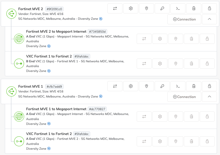
Connections to the same destination should be created on both MVEs and delivered with or without being on the same VLAN. In this example, the Cloud1 VXC (to GCP) will be configured as VLAN 10 on MVE1 and VLAN 11 on MVE2, and the Cloud2 VXC (to AWS) will be configured as VLAN 20 on MVE1 and VLAN 21 on MVE2.
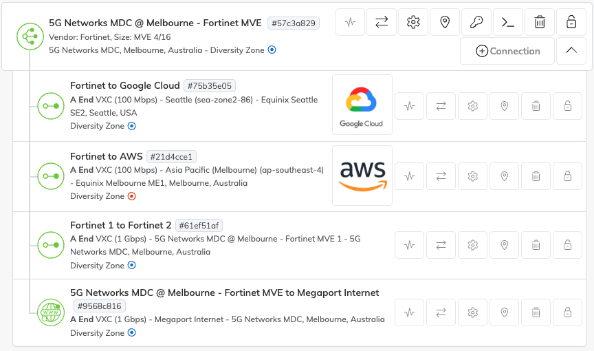
After the VXCs have been created, both MVEs should look similar to the image below.
Configuring interfaces
Now configure the data plane interfaces for the VXCs delivered from Megaport.
For each VXC, create a VLAN subinterface under the data plane interface, such as vNIC 1 - Port 2. Assign the VLAN ID provided by Megaport and configure the appropriate IP addresses for the subinterfaces according to your network design.
For more information, see FortiGate documentation for interface settings.
Configure BGP
Border Gateway Protocol (BGP)Border Gateway Protocol (BGP) is a standardized routing protocol designed to exchange route and reachability information among autonomous systems (AS) on the internet.
is used to distribute and manage routes automatically between the FortiGate MVEs and the connected networks. Each firewall can have different BGP peer addresses and traffic engineering settings.
The virtual router or BGP instance configuration is not synchronized by FGSP, so it must be configured individually on both FortiGate peers.
For detailed information about configuring BGP, see the FortiGate BGP documentation.
BGP manages traffic failover between MVEs while FGSP ensures that active sessions remain synchronized across both devices during a failover. In most cases, enabling Bidirectional Forwarding Detection (BFD) on the BGP peers is recommended to improve failover recovery time. For more information about BFD, see BFD Overview.
FGSP does not handle traffic forwarding; it only replicates session state, so the routing and failover of traffic are managed by BGP, SD-WAN, or any routing policies.
Configure failover conditions
Although FGSP has been configured to synchronize sessions between FortiGate peers, and upstream networks or SD-WAN will redirect traffic to the surviving device in the event of an outage, each firewall and connected network endpoint still needs to know when to consider a peer or path down and how to redirect traffic appropriately.
Failover optimization can be achieved through a combination of mechanisms. BGP with BFD provides rapid route convergence and failover at the routing level. Link monitoring and SD-WAN link health monitoring allow each FortiGate to detect failures on VXCs, cloud connections, or WAN paths and trigger traffic rerouting. In addition, custom scripts or automation can be applied to enforce specific policies or perform additional checks. These mechanisms are not limited to the FortiGate gateways using FGSP; they can also be applied on remote sites or endpoints to improve overall resilience and reduce downtime during failover.
FGSP ensures that active sessions synchronized to the surviving peer are maintained during a failover, but it does not handle traffic redirection itself. Unlike traditional active/passive HA clusters, failover in MVE deployments relies on upstream routing, BGP path monitoring, SD-WAN orchestration, and optional automation to redirect traffic while preserving session continuity. Proper configuration of these mechanisms across both gateways and remote endpoints ensures uninterrupted traffic flow and maximizes network availability.
Review the configuration status
Now that everything is in place and configured, there are a few ways that you can confirm everything is working as expected:
-
All MVEs and VXCs in Megaport Portal should show as live and active.
-
Both firewalls should have BGP sessions established and should be exchanging routes with their peers.
-
Routes for your networks should be present in the routing table and Local Routing Information Base (RIB) of each firewall.
-
Both peers should show as up and reachable, confirming that failover detection at the routing level is operational.
-
Session states should be continuously synchronized between the two FortiGate peers. Each device should maintain an up-to-date view of active sessions, ensuring that traffic can continue uninterrupted if one peer becomes unreachable.
-
Each firewall should correctly monitor the relevant paths using link monitoring or SD-WAN health checks. While the FortiGate MVE operate in standalone mode and do not enter a failover state, verifying that traffic is correctly routed via available paths ensures continuity of network flows.
By verifying MVEs/VXCs, BGP, routes, FGSP session sync, and path monitoring, you can confirm that both traffic forwarding and session continuity are functioning correctly across the FGSP deployment.