Creating an Azure ExpressRoute Connection for an MVE with Cisco SD-WAN
You can create a network connection from an MVE (a Cisco interconnect gateway) to Azure ExpressRoute with Virtual Cross Connects (VXCs). You can create either a private connection or a public (Microsoft) connection.
Important
Before you begin, create an MVE (Cisco interconnect gateway) in vManage based on the Megaport_ICGW_C8000 template. For more information, see Creating a Cisco SD-WAN MVE in vManage.
There are three parts to adding an ExpressRoute connection to your MVE and vManage.
-
Set up your ExpressRoute plan and deploy the ExpressRoute circuit in the Azure console. When deployed, you get a service key. For additional details, see the Microsoft ExpressRoute documentation.
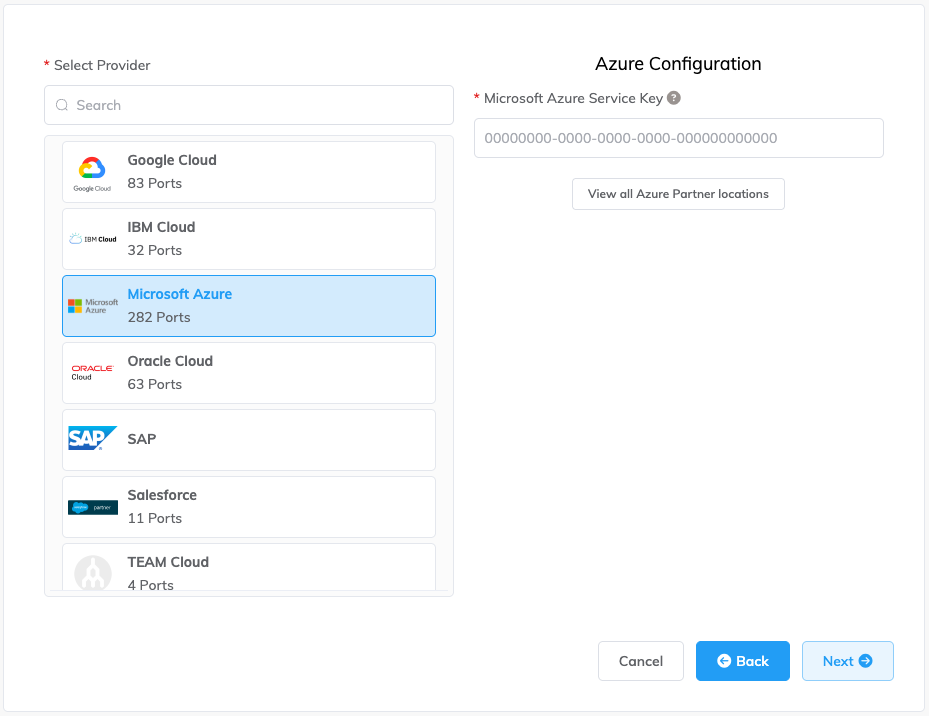
To check the latency and price of connecting to a particular Azure Partner location, start the procedure to add a connection to Microsoft Azure but instead of providing a Microsoft Azure Service Key, click View all Azure Partner locations. You can proceed to the Connection Details page without a service key and review the pricing of the selected port. To place an order for a Microsoft Azure connection, you need to provide a service key.
-
In the Megaport Portal, create a connection (VXC) from your MVE to your ExpressRoute location.
-
In vManage, create a custom MVE device template and add the details of the ExpressRoute connection.
The instructions in this topic describe the second and third parts.
Note
The initial release of MVE requires configuration steps in both Cisco vManage and the Megaport Portal for Azure cloud connections (as described in this topic). Subsequent updates by Cisco let you configure Azure connections completely in vManage. When possible, we recommend creating Azure connections in vManage for seamless integration with your Cisco SD-WAN environment. Cisco provides instructions for the vManage steps: Create Interconnects to Microsoft Azure.
Adding the ExpressRoute connection in the Megaport Portal
To set up the ExpressRoute connection, you need to create the connection in the Megaport Portal.
To create a connection to ExpressRoute from the Megaport Portal
-
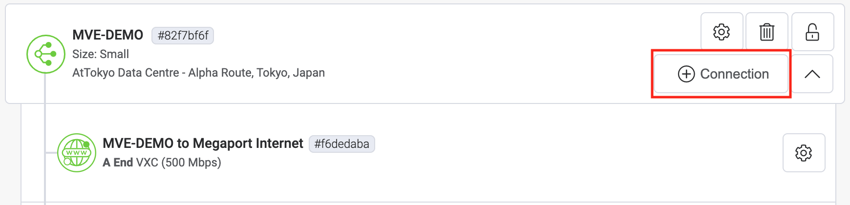
In the Megaport Portal, go to the Services page and select the MVE you want to use.
-
Click +Connection on the MVE.
-
Click the Cloud tile.
-
Select Microsoft Azure as the provider.
-
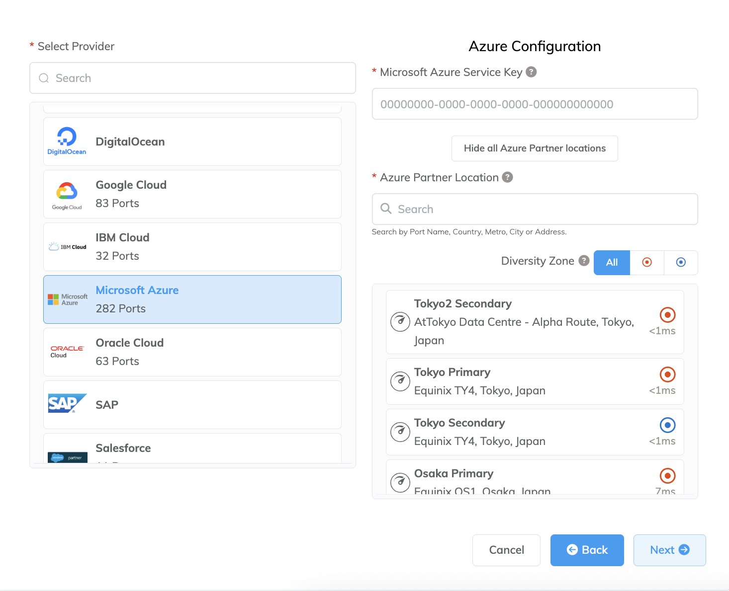
Add the ExpressRoute service key into the Microsoft Azure Service Key field.
The Portal verifies the key then displays the available port locations based on the ExpressRoute region. For example, if your ExpressRoute service is deployed in the Australia East region in Sydney, you can select the Sydney locations. -
Select the connection point for your first connection.
To deploy a second connection (and this is recommended), you can create a second VXC - enter the same service key and select the other connection location.Some helpful links appear on the configuration screen to resources including the Azure Resource Manager console and some tutorial videos.
-
Click Next.
-
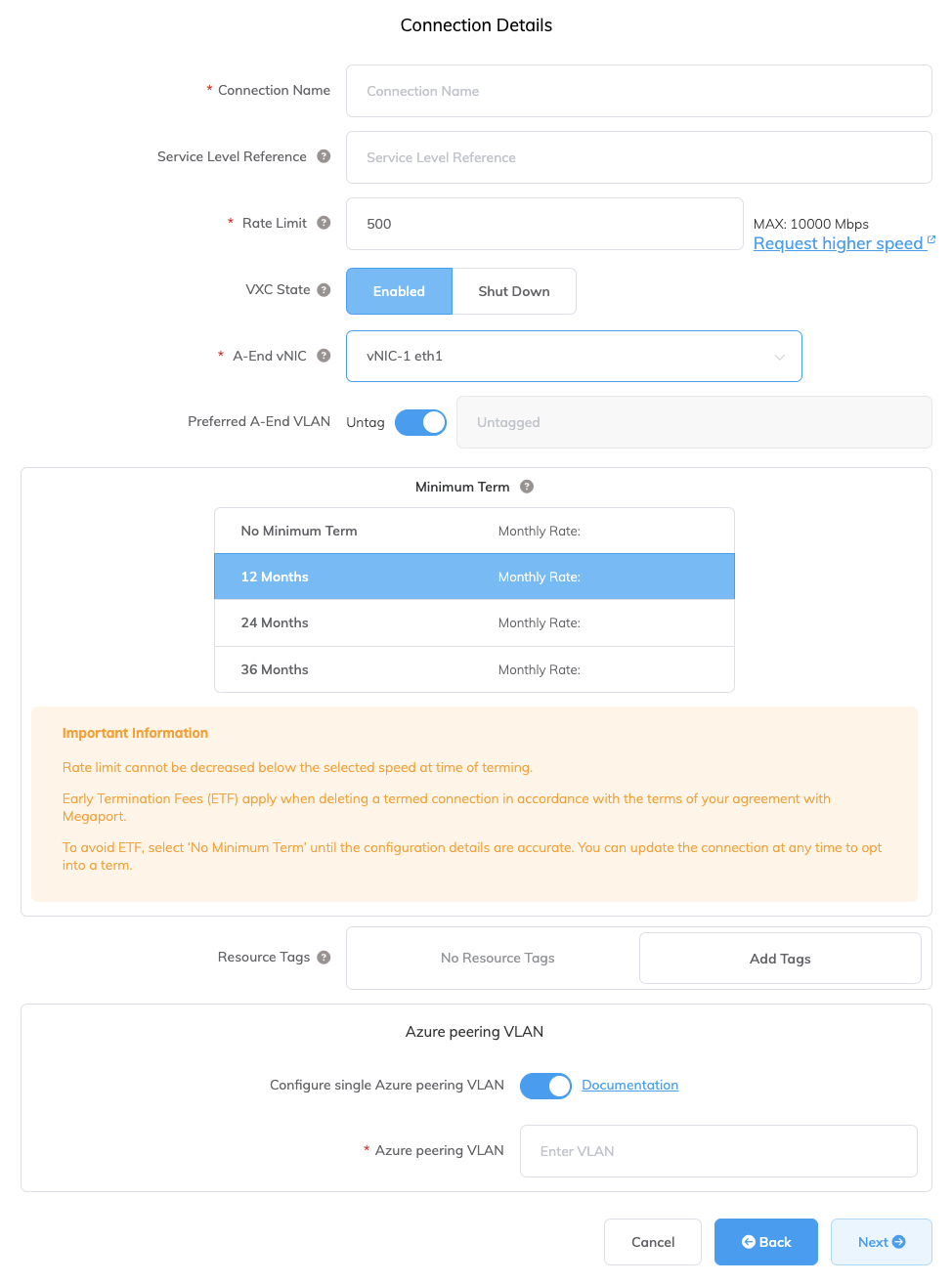
Specify the connection details:
-
Connection Name – The name of your VXC to be shown in the Megaport Portal.
-
Service Level Reference (optional) – Specify a unique identifying number for your Megaport service to be used for billing purposes, such as a cost center number, unique customer ID, or purchase order number. The service level reference number appears for each service under the Product section of the invoice. You can also edit this field for an existing service.
-
Rate Limit – The speed of your connection in Mbps. The rate limit for the VXC will be capped at the maximum allowable based on the ExpressRoute service key.
-
VXC State – Select Enabled or Shut Down to define the initial state of the connection. For more information, see Shutting Down a VXC for Failover Testing.
Note
If you select Shut Down, traffic will not flow through this service and it will behave as if it was down on the Megaport network. Billing for this service will remain active and you will still be charged for this connection.
-
A-End vNIC – Select an A-End vNIC from the drop-down list. For more information about vNICs, see Creating an MVE in the Megaport Portal.
-
Preferred A-End VLAN (optional) – Specify an unused VLAN ID for this connection (for ExpressRoute this is the S-Tag). This must be a unique VLAN ID on this MVE and can range from 2 to 4093. If you specify a VLAN ID that is already in use, the system displays the next available VLAN number. The VLAN ID must be unique to proceed with the order. If you don’t specify a value, Megaport will assign one.
-
Minimum Term – Select No Minimum Term, 12 Months, 24 Months, 36 Months, 48 Months, or 60 Months. Longer terms result in a lower monthly rate. 12 Months is selected by default. Take note of the information on the screen to avoid early termination fees (ETF).
Enable the Minimum Term Renewal option for services with a 12, 24, 36, 48 or 60-month term to automatically renew the contract at the same discounted price and term length at the end of the contract. If you don’t renew the contract, at the end of the term, the contract will automatically roll over to month-to-month contract for the following billing period, at the same price, without term discounts.
For more information, see VXC Pricing and Contract Terms and VXC, Megaport Internet, and IX Billing.
-
Resource Tags – You can use resource tags to add your own reference metadata to a Megaport service.
To add a tag:- Click Add Tags.
- Click Add New Tag.
- Enter details into the fields:
- Key – string maximum length 128. Valid values are a-z 0-9 _ : . / \ -
- Value – string maximum length 256. Valid values are a-z A-Z 0-9 _ : . @ / + \ - (space)
- Click Save.
If you already have resource tags for that service, you can manage them by clicking Manage Tags.
Warning
Never include sensitive information in a resource tag. Sensitive information includes commands that return existing tag definitions and information that will identify a person or company.
-
Configure Single Azure Peering VLAN – By default, this option is enabled for MVE.
This option provides a single tag VLAN solution. You configure peering in Azure with the MVE VLAN (A-End) and the peer VLAN set in Azure (B-End). Note, you can have only one peering type (Private or Microsoft) per VXC with this option. If you want to set up an inner VLAN and Q-n-Q, turn off this option. -
Azure Peering VLAN – This value needs to match the A-End VLAN for single tag VLAN peering. A different Azure peering VLAN can also be set, if required.
-
-
Click Next to proceed to the connection detail summary, then click Add VXC.
-
Click Review Order to proceed through the checkout process, or click Save to save the configured services before placing the order.
-
Review the Important Information section and confirm agreement with the Service Agreements.
If you do not have a promotion code, skip to the Order Now step. If you do have a promotion code, enter it into the Enter discount code field then click Apply. Alternatively, if a code already appears in the Discounts field, verify it is correct and click Apply.
The promotional discount appears below the Standard Term discount. This discount is not reflected in the Monthly Rate shown here, it is applied at the time of billing. If an invalid or expired code causes an error with your order, contact your Megaport Account Manager for a replacement code.
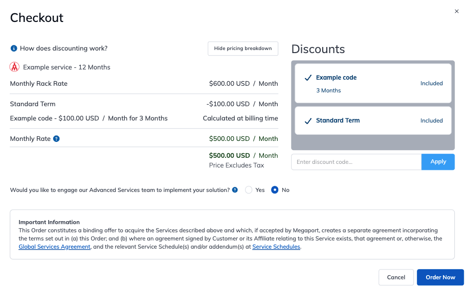
If you entered an incorrect promotion code, you can remove it by clicking Remove.
-
Click Order Now.
When the VXC configuration completes, the VXC icon is green.
![]()
In the Azure Resource Management console, the provider status will be Provisioned.
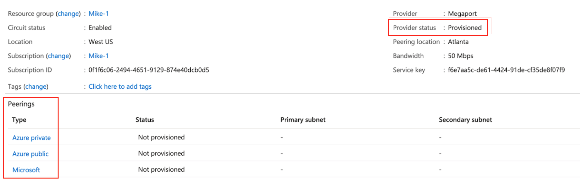
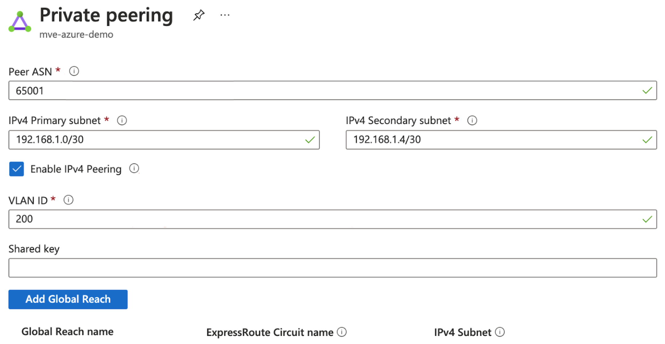
When provisioned, you need to configure peerings. You can configure private and Microsoft peering. Click the peer to configure and provide these details:
- Peer ASN – Enter the ASN for the MVE.
- IPv4 Subnets – From each of these subnets, MVE uses the first usable IP address and Microsoft uses the second usable IP for its router.
- VLAN ID – Enter the second .1Q value configured for the connection in the vManage CLI add-on template.
- Shared Key – This value is not required.
Adding the ExpressRoute connection to vManage
Follow the steps in each of these sections to create, edit, and attach the vManage templates for an MVE with the connection details.
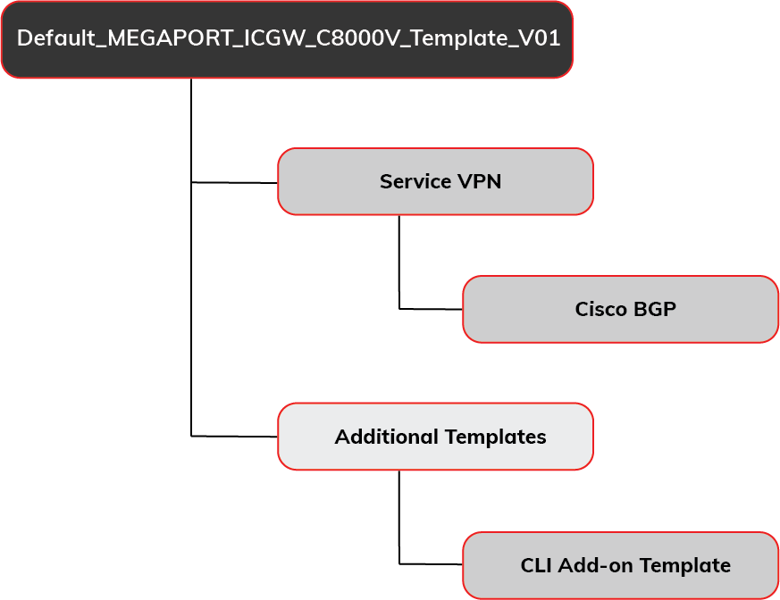
To set up the connection in vManage, you need a dedicated device template and you need to provide feature templates for device-specific configuration details. You need to create a Service VPN template, a Cisco BGP template, as well as a CLI add-on template.
Step 1 – Copy the default device template
You need a dedicated template for the MVE so you can edit the template with the connection details for the VXC. You need a dedicated template because if other devices are attached to the template, the change affects each attached device.
To create a copy of the device template
-
In vManage, go to Configure > Templates and select the Device tab.
-
Find the Default_MEGAPORT_ICGW_C8000V_Template_V01 template and copy it.
Click the ellipsis (…) at the end of the row and choose Copy from the drop-down menu. -
Enter a name for the template and a description and click Copy.
This name can contain only uppercase and lowercase letters, the digits 0 through 9, hyphens, and underscores. It cannot contain spaces or any other characters.
Step 2 – Create a Cisco VPN feature template
You need to create a VPN template so you can specify the VPN ID of the GCP connection. The VPN ID is the same as the corporate network.
To create a VPN feature template
-
In vManage, go to Configure > Templates and select the Feature tab.
-
Find a template for the C8000v device model and a type of Cisco VPN and copy it.
Click the ellipsis (…) at the end of the row and choose Copy from the drop-down menu.Note
Instead of copying the template, you can also add a new Cisco VPN template for a C8000v device and populate it with the same values.
-
Enter a name for the template and a description and click Copy.
-
Edit the template and add the VPN ID in the Basic Configuration.
Click the ellipsis (…) and choose Edit.
The VPN ID can be any number 1 – 511 or 513 – 65530. VPN 0 is reserved for Transport VPN and VPN 512 is reserved for Managed VPN. The number is normally identical to the VPN ID assigned for corporate networks to communicate between the corporate network and cloud service. -
Click Update.
Step 3 – Create a BGP feature template
You also need a BGP template for the connection peering details.
To create a Cisco BGP feature template
-
In the Feature tab of vManage Templates, find a template for the C8000v device model and a type of Cisco BGP and copy it.
Note
Instead of copying the template, you can also add a new Cisco BGP template for a C8000v device and populate it with the same values.
-
Enter a name for the template and a description and click Copy.
-
Edit the template (click the ellipsis … for the new template and choose Edit) and enter the AS Number for the MVE in the Basic Configuration section.
This value is device specific. -
In the Neighbor section, click +New Neighbor and specify these values for the cloud side of the connection:
- Address – Specify the peer IP address of the cloud side.
- Description – Enter a meaningful description of the template.
- Remote AS – Enter the AS Number of the cloud side: the AS number of Azure is 12076.
-
Click Update.
Step 4 – Create a CLI Add-On feature template
You also need an add-on CLI template.
To create a CLI Add-On feature template:
-
Find a template for the C8000v device model and a type of CLI Template and copy it.
The CLI template configures the subinterface for the MVE. -
Enter a name for the template and a description and click Copy.
-
Edit the template (click the ellipsis … for the new template and choose Edit) and copy the following lines into the CLI Configuration section.
If you enabled Single Azure Peering VLAN:
interface GigabitEthernet1. {{interface-tag}}
encapsulation dot1Q {{dot1Q-tag-s-tag-01}}
vrf forwarding 100
ip address {{ip-address-subinterface-01}}
ip mtu 1500
!
If you did not enable Single Azure Peering VLAN:
interface GigabitEthernet1. {{interface-tag}}
encapsulation dot1Q {{dot1Q-tag-s-tag-01}} second-dot1q {{dot1Q-tag-c-tag-01}}
vrf forwarding 100
ip address {{ip-address-subinterface-01}}
ip mtu 1500
!
Here’s an explanation for each line.
CLI Entry Description interface GigabitEthernet1. {{interface-tag-01}} A description field for the sub interface. encapsulation dot1Q {{dot1Q-tag-s-tag-01}} second-dot1q {{dot1Q-tag-c-tag-01}} The first dot1Q is the S-tag. This tag is set as the A-End tag with the VXC in the Megaport Portal. The second dot1Q is the C-tag. This tag is set in the Azure console with the peer. (If you have Single Azure Peering VLAN enabled, you do not need to configure the second dot1Q interface.) vrf forwarding This is the VPN for your peer. This example defines VPN 100 and adds it to the template. ip address {{ip-address-subinterface-01}} The IP address of the interface - assigned by Microsoft. ip mtu ExpressRoute supports an MTU value of 1500. -
Click Update.
Step 5 – Update your device template
Next, we need to add the feature templates to the copy of the default device template and then define the values for the added features.
To add the feature templates to the device template
-
In the Device tab of vManage Templates,find the copy of the device template that you created in Step 1 and click the ellipsis (…) and choose Edit.
-
In the Service VPN tab, click +Add VPN.
-
In the Available VPN Templates, highlight the template created in Step 2, click the arrow to move it to the Selected VPN Templates, and click Next.
The select sub-templates step appears. - From the Additional Cisco VPN Templates, click Cisco BGP.
- From the Cisco BGP menu, choose the BGP template you created in Step 3 and click Add.
-
In the Additional Templates tab, select the CLI Add-On template you created in Step 4 and click Update.
A screen appears that lists the updated device template. You need to edit this template to add values for the new fields and associate an MVE. -
Click the ellipsis (…) and choose Edit.
The device settings appear with new fields defined in the feature templates.
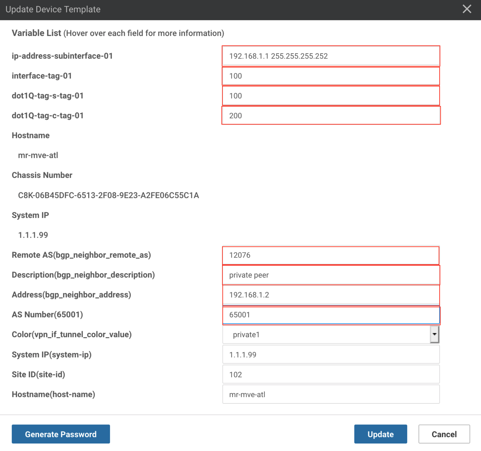
- Enter values for these new fields:
- ip-address-subinterface – Specify the IP address of the interface. This is the first IP address from the /30 Primary subnet assigned with the peer in the Azure console.
- interface-tag – This value is the same as dot-1q-s-tag. You can find this value in the VXC connection details on the Megaport Portal: click the gear icon for the VXC, choose Details, and use the A-End VLAN value.
- dot-1q-s-tag – The dot1Q S-tag. This value is the same as interface-tag. You can find this value in the VXC connection details on the Megaport Portal: click the VXC name, choose Details, and use the A-End VLAN value. (If you have Single Azure Peering VLAN enabled, you do not need to configure this interface.)
- dot-1q-c-tag – The dot1Q C-tag. This tag is set in the Azure console with the peer.
- Remote AS(bgp_neighbor_remote_as) – The AS number for ExpressRoute is 12076.
- Description(bgp_neighbor_description) – Enter a meaningful description of the template for the BGP peer.
- Address(bgp_neighbor_address) – Specify the peer IP address of the ExpressRoute MSEE router. This is the second available IP address from the /30 Primary subnet assigned with the peer in the Azure console.
- AS Number – Specify the AS number of the MVE.
-
Click Update.
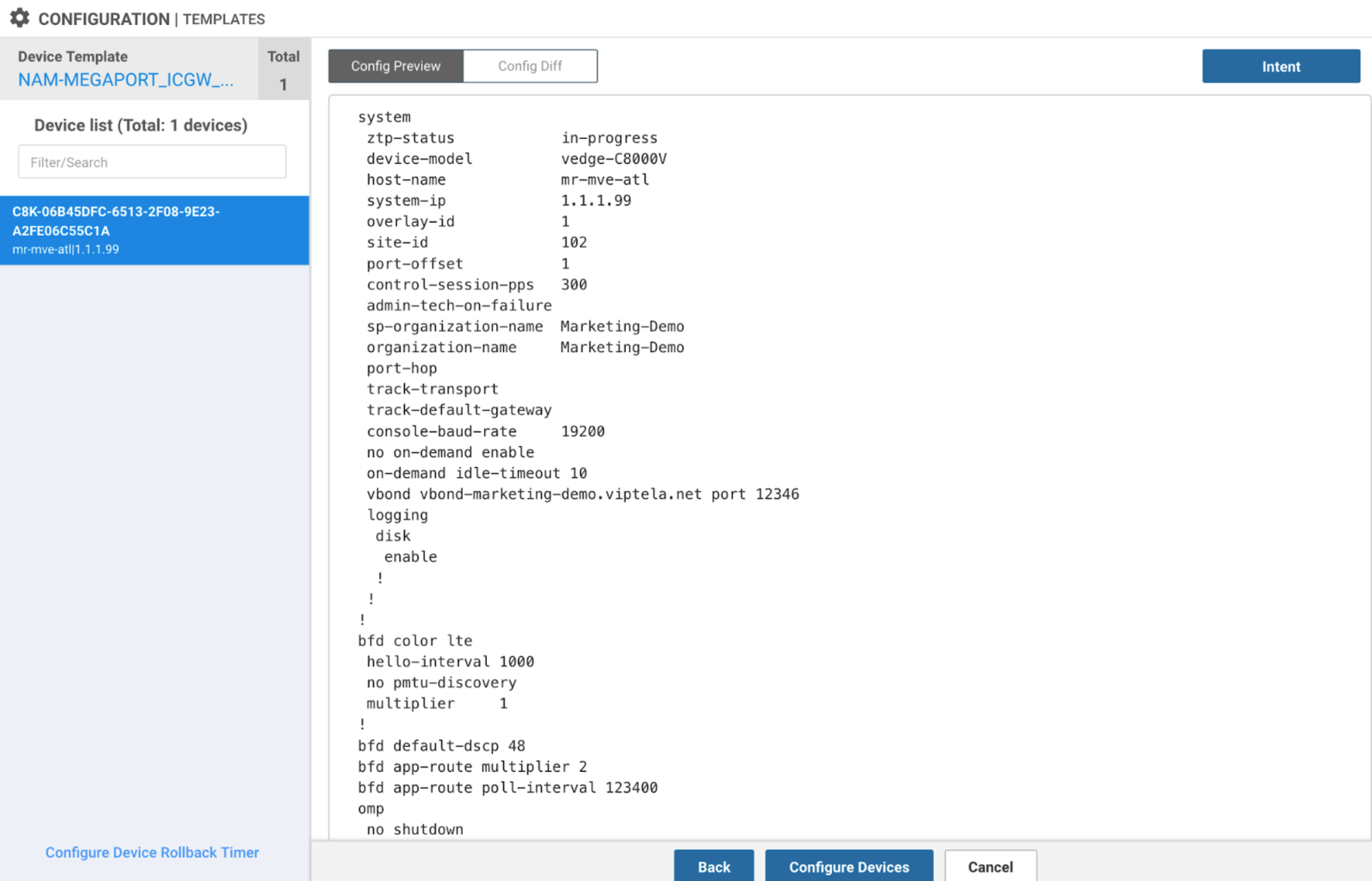
vManage displays a preview of the configuration. Click Config Diff to review the changes. (Changes are highlighted in green.) -
Select the MVE in the device list.
-
Review the changes and click Configure Devices.
vManage loads the template. When complete, the status indicates success.
Verify the ExpressRoute connection
You can verify the ExpressRoute connection from the Azure console. Review the ARP and route table.
You can also verify from vManage.
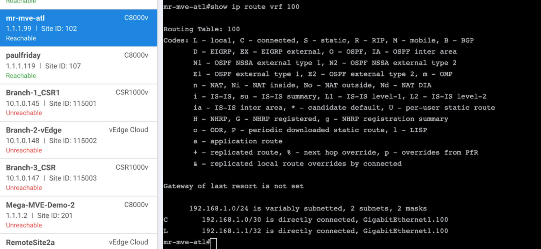
To verify from vManage
- Go to Tools > SSH Terminal and log in to your MVE.
- Enter the following command to see the routes advertised by the VPN peer:
show ip route vrf 100
Adding a secondary connection
To add a secondary VXC, repeat the process of adding a VPN to the device template and update the CLI template with a second subinterface.
interface GigabitEthernet1. {{interface-tag}}
encapsulation dot1Q {{dot1Q-tag-s-tag-01}} second-dot1q {{dot1Q-tag-c-tag-01}}
vrf forwarding 100
ip address {{ip-address-subinterface-01}}
ip mtu 1500
!
interface GigabitEthernet1. {{interface-tag}}
encapsulation dot1Q {{dot1Q-tag-s-tag-01}} second-dot1q {{dot1Q-tag-c-tag-01}}
vrf forwarding 100
ip address {{ip-address-subinterface-01}}
ip mtu 1500
!