Configuring High Availability on Palo Alto Networks VM-Series Firewall
This topic describes the steps to configure Palo Alto Networks Active/Active High Availability (HA) with route based redundancy.
Palo Alto Networks provides documentation for VM-Series at VM-Series Tech Docs.
Basic steps
This section provides an overview of the configuration steps in the Megaport Portal and PAN-OS. Procedures follow this basic step summary.
The basic steps are:
-
Create a Palo Alto Networks MVE.
Palo Alto Networks HA requires three dedicated HA interfaces (HA1, HA2, HA3), and the management and data plane interfaces. Add additional vNICs for a total of 5. -
Create a second Palo Alto Networks MVE of the same size and version, within the same metro. Palo Alto Networks requires the MVEs to be the same size, and to be within 20 milliseconds of each other. For HA prerequisite details, see Prerequisites for Active/Active HA.
-
Create the VXCs for HA traffic.
vNIC 1 is for management, vNIC 2 for data plane, and vNIC 3 through 5 for dedicated HA traffic. Create a VXC between vNIC 3 (HA1) on each MVE, both ends should be untagged (no VLAN). Repeat for vNICs 4 (HA2) and 5 (HA3).
We recommend the HA1 and HA2 VXCs are configured at 1 Gbps, and the HA3 VXC configured with a speed to allow it to carry the expected combined total traffic routed through the firewall. -
Configure Active/Active HA in the Palo Alto Networks PAN‑OS software.
For more information, see the Palo Alto Networks documentation at Configure Active/Active HA.
HA Overview
When deploying Palo Alto Networks next-generation firewalls (NGFW) on premises or in a data center, using the built in High Availability (HA) functionality is a common approach. PAN-OS HA is a robust solution that solves several challenges with redundant firewalls, in particular session state and configuration synchronization.
Historically this architecture has been hard to achieve in cloud environments as it relies on specific network functionality which often is not available. Megaport’s support of Palo Alto Networks firewalls on Megaport Virtual Edge (MVE), and multi vNIC functionality on the MVE platform, makes this architecture possible. This solution is particularly useful for customers using MVE for a virtualized network core and/or multicloudThe use of multiple cloud computing services in a single heterogeneous architecture. For example, an enterprise might use multiple cloud providers for infrastructure (IaaS) and software (SaaS) services. One of Megaport’s core value propositions is enabling multicloud connectivity.
connectivity.
Palo Alto Networks firewalls deployed on MVE can be configured with Active/Active HA, combining the benefits of on-demand as-a-service deployment, direct private connectivity to clouds and data centers, optimal resource utilization, session and configuration synchronization, and orchestrated failover.
Active/Active HA
PAN-OS has two modes of HA:
- Active/Active
- Active/Passive
Active/Passive HA has only one firewall active at any one time, with the secondary firewall having all interfaces disabled and passing no traffic. This makes sense when working with a pair of devices in the same location connected to the same physical switches, and has the advantage that it doesn’t add complexity in simple architectures (like you might find in an office).
Active/Active HA allows both firewalls to be active and passing traffic at the same time, with all traffic being redirected to the remaining device if a firewall or monitored link fails. This has the advantage of allowing the rest of the network to be aware of the available paths, and of being able to use the capacity of both firewalls in a normal state.
Active/Active HA in PAN-OS uses routing and/or NAT to distribute traffic between both firewalls, while synchronizing the active sessions between both devices. Each firewall has its own interfaces with its own BGP sessions, and ECMP can be used to balance traffic across both devices. In the event of a failover, routes are updated, flows are redirected, and the remaining firewall picks up the existing sessions.
A failover can be triggered either by one of the firewalls failing, a monitored path becoming unavailable, or a failure of the HA links between the devices. If a monitored path becomes unavailable, traffic is forwarded from the affected device to the device with the available path via the HA3 link.
See the Palo Alto Networks documentation for more information about PAN-OS Active/Active HA at Use Case: Configure Active/Active HA with Route-Based Redundancy.
Understanding the architecture
The architecture deployed in this topic is shown below.
There are two MVEs running Palo Alto Networks PAN-OS, each with their management interface connected to the internet. Three VXCs are connected between the two MVEs for the HA links, and the data plane VXCs are connected to two different cloud environments, which are connected together.
Note
In a production deployment, there might be additional data plane VXCs to connect to other networks, internet connections, VPNs, and so on, and the management interfaces might be on private networks instead.
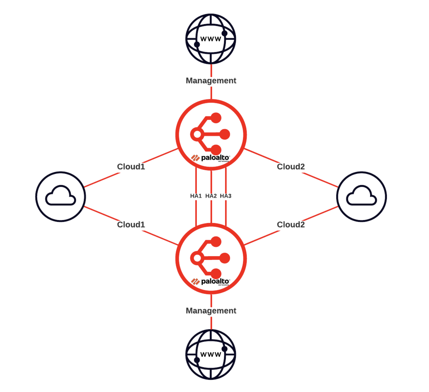
Architecture overview
This image shows a high level architecture diagram of the Palo Alto Networks Active/Active HA solution.
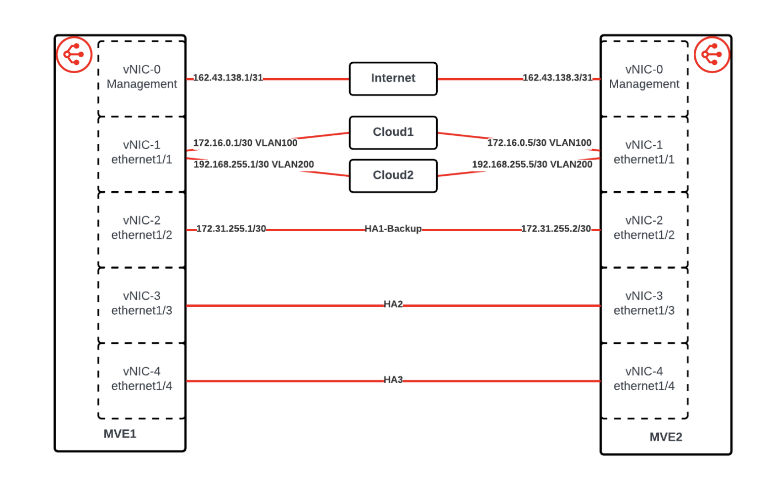
Interface details
This image shows the interface details for the Palo Alto Networks Active/Active HA solution.
Create the Palo Alto Networks VM-Series MVEs in the Megaport Portal
The first step is to create and deploy two MVEs in the Megaport Portal. Palo Alto Networks HA requires three dedicated HA interfaces (HA1, HA2, HA3), as well as the management and data plane interfaces.
To create and deploy Palo Alto Networks MVEs
-
In the Megaport Portal, go to the Services page.
-
Create a Palo Alto Networks MVE as described in Creating a VM-Series MVE.
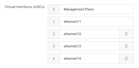
-
On the MVE Details screen, make sure that you create five vNICs in the Virtual Interfaces (vNICs) field to support the additional interfaces used for HA.
-
Create a second Palo Alto Networks MVE of the same size and version, in another data center within the same metro. Palo Alto Networks requires the MVEs to be the same size, and to be within 20 milliseconds of each other. This MVE must also have five vNICs added.
-
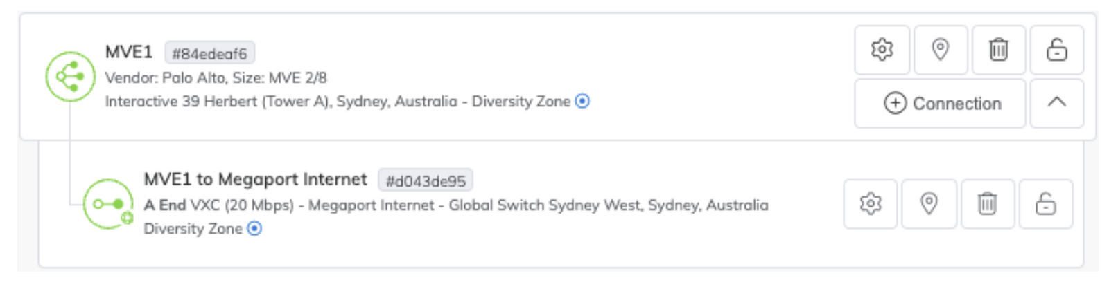
For management access, create a Megaport Internet connection for the management interface of each MVE.
This is the most common approach during initial deployment, but the management interface can instead be connected to a private VXC once an alternative management path is configured.
Once completed, there should be two MVEs deployed which both look like this:
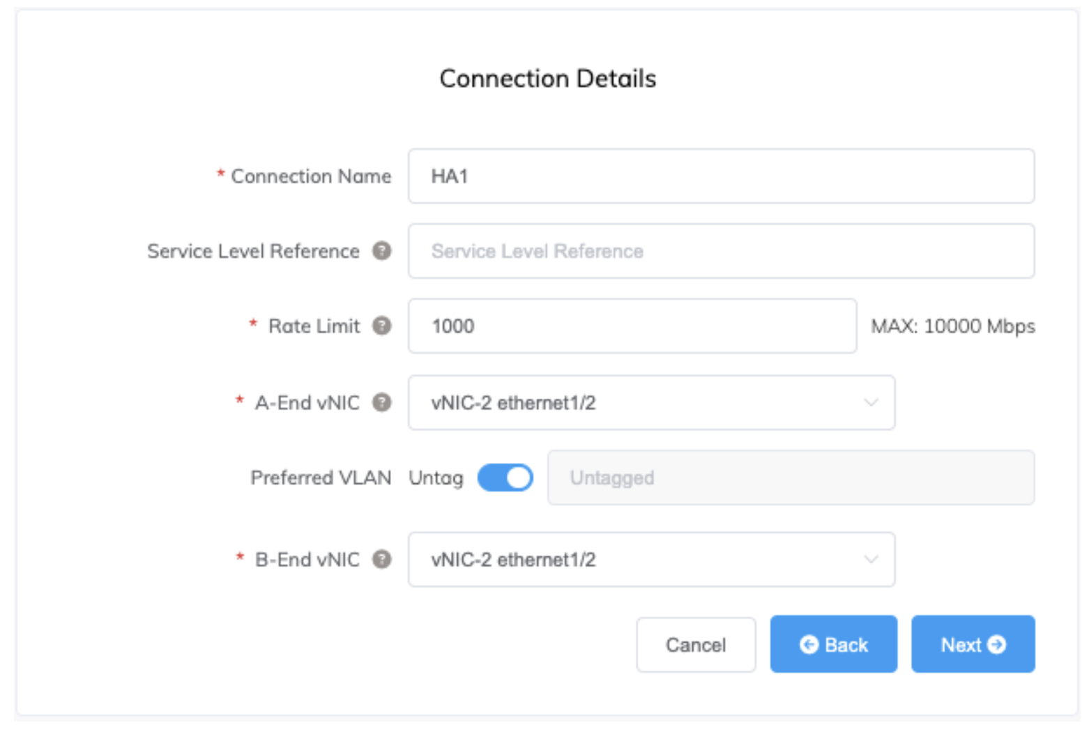
Create the VXCs for HA traffic
Now that the MVEs have been created, the next step is to create three private VXCs for HA traffic between the two devices. Use ethernet1/2, ethernet1/3, and ethernet1/4 for the HA interfaces, connecting each one to the same interface on the other MVE, and configuring the VXCs as untagged.
For HA1 and HA2, create a 1 Gbps VXC for each. The bandwidth requirements for HA3 can be significant, especially during a path outage, so create a 10 Gbps VXC for that path.
To create a VXC between MVEs
-
In the Megaport Portal, go to the Services page.
-
Create a VXC between two Palo Alto Networks MVEs as described in Connecting MVEs Integrated with Palo Alto VM-Series.
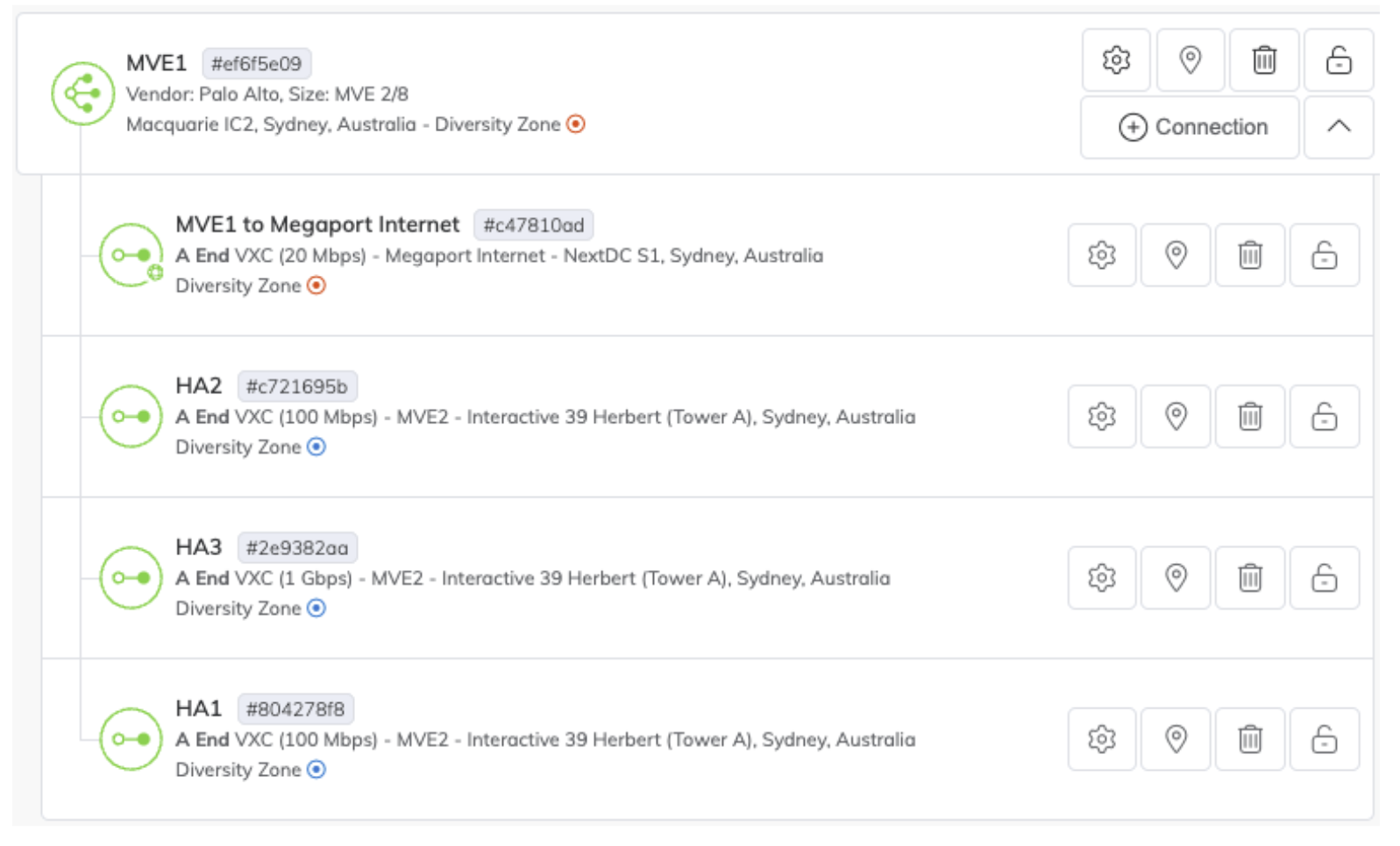
-
Repeat this process to create untagged VXCs between the three interfaces on each MVE being used for HA. Each MVE should now look similar to the image below:
Configure Active/Active HA in PAN-OS
Now that the underlying infrastructure has been created and configured in the Megaport Portal, the firewalls need to be configured in the Palo Alto Networks PAN‑OS software. The management web interface for each firewall can be accessed on the IP of the VXC attached to the management vNIC (vNIC0) (you can find the IP on the Details tab of the VXC).
This section describes the configuration of Active/Active HA in PAN-OS based on version 10.2. This should be used as an example only. Modifications to the configuration within the firewalls might be required for your environment and/or based on updates or changes released by Palo Alto Networks in future. In general, you should see the Palo Alto Networks documentation for detailed information about the available options and best practices in PAN-OS.
Configure Hypervisor assigned MAC addresses
By default, PAN-OS will use self generated MAC addresses for the ethernet interfaces. This prevents successful configuration of HA as both firewalls will have the same MAC addresses. To prevent this, enable the option to use Hypervisor Assigned MAC Addresses. This will cause PAN-OS to use the real MAC address of the underlying hardware interfaces which will be different on each MVE.
For more information, see the Palo Alto Networks documentation at Hypervisor Assigned MAC Addresses.
Configure static management IPs
Palo Alto Networks’ recommended design for HA on VM-Series appliances is to use the management interface for HA1. To be used for HA, an interface must have a static IP as using DHCP for HA is not supported by PAN-OS. By default, the management interface of an MVE uses DHCP to acquire its IP address, so this must be changed to static. When the management interface is configured with a static IP, static DNS servers must also be configured. As jumbo frames will be enabled, confirm the MTU of the management interface is set to 1500.
If you are using the provided Megaport Internet connection for management, although the IP is provided by DHCP by default, it is a persistent address and will not change as long as the Megaport Internet connection exists. The IP address, subnet mask, and gateway can be found in the Details section of the connection in the Megaport Portal. Configuring IPv6 is optional.
For more information about how to configure interfaces in PAN-OS, see the Palo Alto Networks documentation at Configure Management Interface IP.
Enable jumbo frames
As the HA3 link sends encapsulated traffic between the firewalls, it requires an MTU greater than 1500 bytes. To achieve this, jumbo frames must be enabled globally. After jumbo frames are enabled globally, all interfaces will default to the higher MTU. If you want data plane interfaces to remain at an MTU of 1500, you need to specify the MTU for each interface. Megaport VXCs support an MTU of up to 9100.
For more information about how to enable jumbo frames, see the Palo Alto Networks documentation at Enable Jumbo Frames on the VM-Series Firewall.
Create a virtual router
The next step on each firewall is to create a virtual router. This is required in PAN-OS regardless of whether the device is physical or virtual, standalone, or in HA. A virtual router represents a single route table.
For more information about creating virtual routers, see the Palo Alto Networks documentation at Configure Virtual Routers.
Create a zone
Layer 3 interfaces must be added to zones before they become functional.
See the Palo Alto Networks documentation for detailed information on zones at Segment Your Network Using Interfaces and Zones.
Configure interface types
Next, configure the interfaces as the required type. Interface ethernet1/1 will be configured as Layer 3 (this will be used to connect to workloads), and interfaces ethernet1/2, ethernet1/3, and ethernet1/4 will be configured as HA.
For more information, see the Palo Alto Networks documentation at Firewall Interfaces Overview.
Configure HA
Now that the basic infrastructure is in place, we can configure the HA functionality.
See the Palo Alto Networks documentation for detailed information on Active/Active High Availability at Configure Active/Active HA.
Create data plane connections
Now that the MVEs are in place and configured in HA, create some data plane VXCs to connect to the networks we want to route between. The data plane VXCs will be attached as tagged VLAN subinterfaces of ethernet 1/1, and the relevant subinterfaces and BGP peers will be configured within the firewalls.
In this example we’ll connect AWS and Azure, but the same process can be used to connect any networks that are reachable through a VXC. Some tasks are performed in the Megaport Portal and some in PAN-OS.
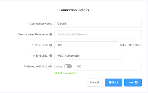
Create VXCs
The VXCs are created in the Megaport Portal using the standard process as described in Connections Overview, specifying vNIC-1 ethernet1/1 for the A-End vNIC and configuring the VXC to be delivered as a tagged VLAN.
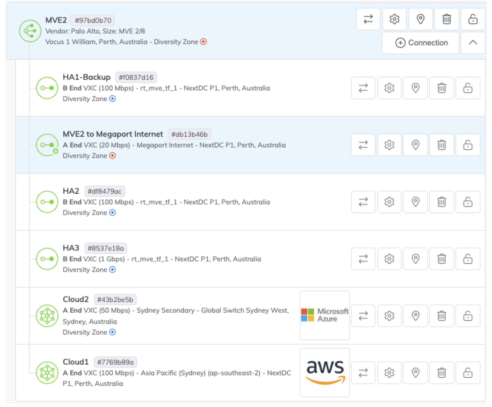
Connections to the same destination should be created on both MVEs and delivered as the same VLAN. In this example, the Cloud1 VXC (to AWS) will be configured as VLAN 100 on both MVEs, and the Cloud2 VXC (to Azure) will be configured as VLAN 200.
After the VXCs have been created, both MVEs should look similar to the image below.
Configure interfaces
Now configure the data plane interfaces for VLANs 100 and 200 in PAN-OS. Subinterfaces for each VLAN will be created under ethernet1/1.
See the Palo Alto Networks documentation for detailed information on configuring interfaces at Configure Interfaces.
Configure BGP
BGP will be used to distribute and manage routes automatically, including load balancing and managing the failover of traffic from one firewall to the other during an outage. Although BGP will manage redirecting the traffic, existing sessions will be maintained as the HA functionality will keep the session state in sync between both firewalls.
As each firewall will use different peer addresses and might use different BGP settings for traffic engineering, the Virtual Router settings are not synchronized between devices and must be configured on both.
See the Palo Alto Networks documentation for detailed information on configuring BGP at Configure BGP.
In most cases, we also recommend enabling Bidirectional Forwarding Detection (BFD) to improve failover recovery time. For more information about BFD, see BFD Overview.
Configure failover conditions
Although what has been configured already will synchronize sessions between devices, and the external peers will direct traffic to the remaining device in the event of an outage, we still need to tell each firewall when to consider itself down and for the remaining firewall to pick up the sessions that have been synchronized to it.
This is achieved by configuring Virtual Router Path monitoring. Each firewall is configured to monitor relevant paths, and when those paths go down, to forward traffic via the other device through the HA3 link.
See the Palo Alto Networks documentation for detailed information on configuring failover conditions at Define HA Failover Conditions.
Review the configuration status
Now that everything is in place and configured, there are a few ways that you can confirm everything is working as expected.
-
Both MVEs and all VXCs in the Megaport Portal should be green.
-
All indicators on the HA widget on the Dashboard tab of both firewalls should be green.
-
Both BGP sessions on both firewalls should be Established.
- Network > Virtual Routers > More Runtime Stats > BGP > Peer
-
Routes for your networks should be received from both peers on both firewalls.
- Network > Virtual Routers > More Runtime Stats > BGP > Local RIB
-
If BFD has been configured, both peers on both firewalls should be up.
- Network > Virtual Routers > More Runtime Stats > BFD Summary Information
-
Routes for your networks should be in the route table on both firewalls.
- Network > Virtual Routers > More Runtime Stats > Routing > Route Table
-
Sessions from both firewalls should appear in the Session Browser on both devices, with synchronized sessions marked as Session From HA: True.
- Monitor > Session Browser
-
Each firewall should enter Tentative (Path down) mode if any of the monitored paths on that device fail.
- Dashboard > High Availability widget