Creating MVE Connections to Any Endpoint with Versa Secure SD-WAN
This topic describes the general steps to configure and deploy a Megaport VXC connection in the Megaport Portal and integrate it with an MVE in Versa Secure SD-WAN. The VXC can connect to a Cloud Service Provider, a Port, or an MCR.
Step 1: Create an MVE
- Create an MVE in the Megaport Portal.
For more information, see Creating an MVE. The MVE needs to be in the active state.
Step 2: Create a VXC from the MVE
- In the Megaport Portal, select the MVE created in Step 1.
- Create a VXC to another MVE, a Port, or Cloud Service Provider.
For more information, see Creating a VXC. Ensure both ends of the connection are active and have BGP configured. - In the connection details, note the A-End VLAN.
Step 3: Collect these values for the connection
- MVE IP address
- MVE VLAN (A-End)
- MVE ASN
- Cloud/B-End IP address
- B-End ASN
- MD5 Password
Step 4: Create an interface in Versa Director
-
Log in to Versa Director.
-
Select the Workflows tab in the top menu bar.
-
Select Template > Templates in the left menu bar.
-
Select the template associated with this device.
-
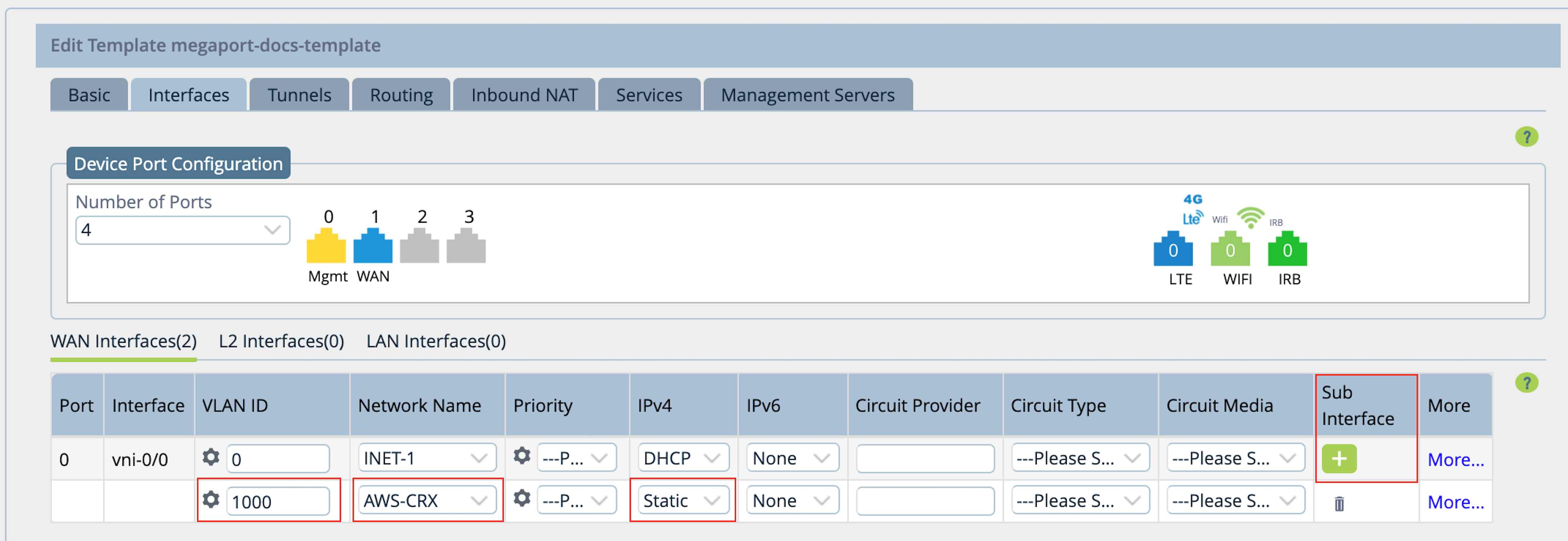
Select the Interfaces tab.
-
Under WAN Interfaces, click
 (Add) to add a subinterface.
 -
In the VLAN ID field, enter the VLAN value from the Megaport Portal.
Specify the A-End VLAN for the connection - click the details icon for the connection in the Portal to find this value. -
In the Network Name column, choose + Create WAN Network from the menu.
Or select a previously created network, if appropriate. -
For a new network, enter a name and optionally, a description.
-
Click OK.
-
In the IPv4 column, choose Static from the menu.
-
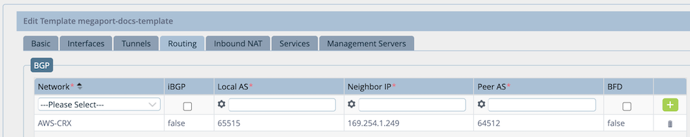
Select the Routing tab.
-
In the BGP section, select the network created earlier.
-
Enter in the following values for your connection:
- Local AS – The AS value for the A-End of the connection.
- Neighbor IP – The IP address of the B-End of the connection (cloud provider, port, or other MVE).
- Peer AS – The AS value for the B-End of the connection.
- Optionally, enable BFD.
-
Click
(Add).
-
Click Recreate at the bottom of the page.
A screen appears that highlights the differences in the configuration. -
Click Deploy.
-
Select the Configuration tab in the top menu bar.
-
Select Templates > Device Templates in the horizontal menu bar.
-
Click the template you want to modify.
-
In the side navigation, select Interfaces.
-
Click the vni-0/0 interface.
-
Click the VLAN value of the new subinterface.
-
In the Static Address section, click
 (Parameterize) to use a variable for the static IP address value. (This is enabled by default.)
When parameterized, the icon is green. Click it if you need to change it. The parameterized field ensures each device associated with the template has a unique variable for the IP address.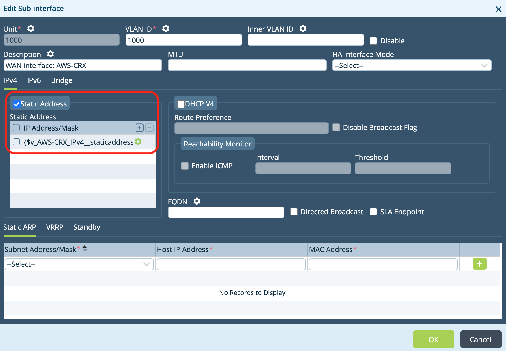
-
Click OK two times to update the VNI.
-
In the side navigation, select Virtual Routers.
-
Click the Transport-VR link for your network.
-
In the side navigation, select BGP.
-
Click the Instance ID for your network.
-
Click
(Parameterize) to use variables for the Router ID and the Password fields. -
Click OK two times to return to the main window.
Step 5: Configure the device
-
Select the Workflows tab in the top menu bar.
-
Select Devices > Devices in the left navigation.
-
Click the device to modify.
-
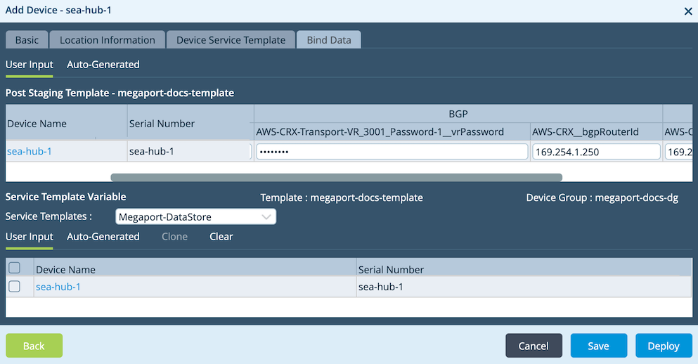
Select the Bind Data tab.
-
Enter the values for Static Address, BGP Password, and BGP Router ID.
Other values, such as the Local and Peer AS are auto-populated from our earlier settings.
-
Click Deploy.
-
In the upper right of the screen under your username, click Commit Template.
-
Select your Organization and Template.
In the lower part of the screen, the Template State will be OUT-OF-SYNC.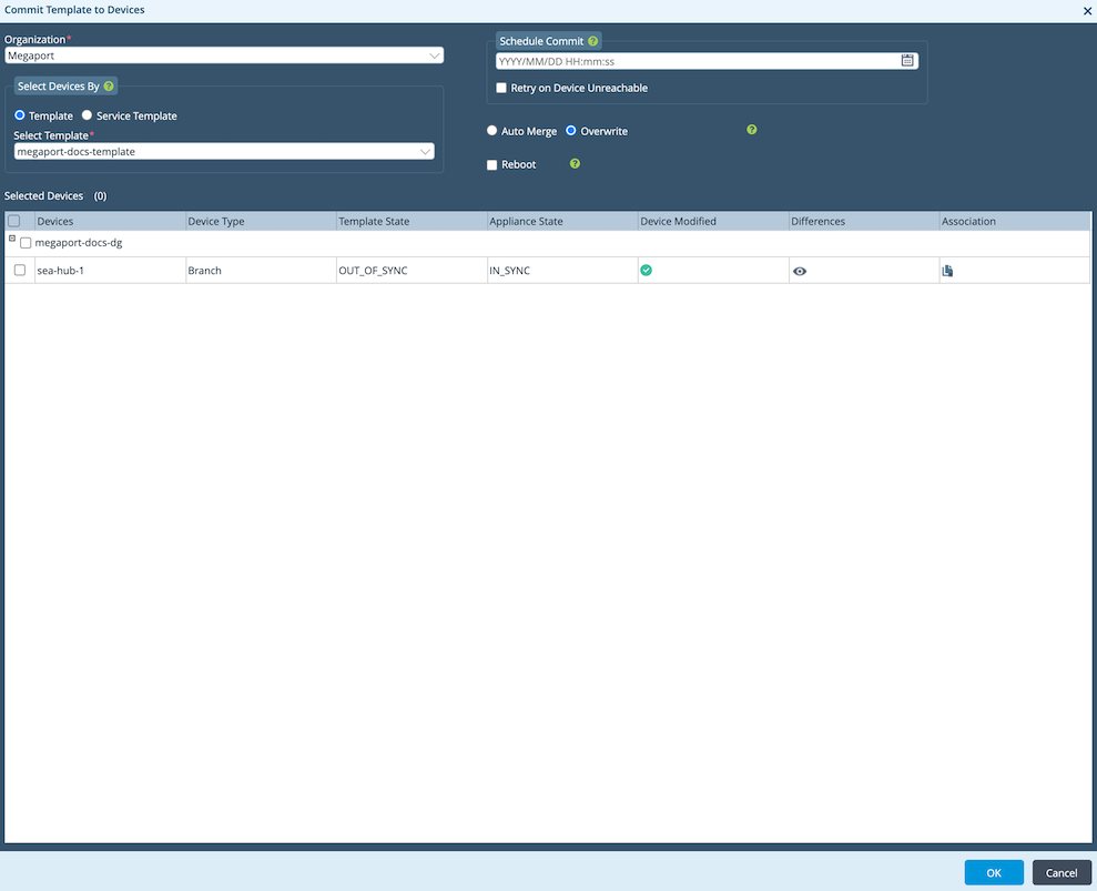
-
Click the eye icon in the Differences column.
A page appears that highlights the differences in the configuration. -
If you are satisfied with the configuration, click Commit to Device.
Step 6: Validating your connection
You can review device status, including the connection state, from the Monitor tab in Director.
-
Select the Monitor tab in the top menu bar.
-
Select Devices in the horizontal menu bar.
-
Click the device to review status and activity.