Configuring AWS Outposts Rack with Private Connectivity
This topic describes how to deploy AWS Outposts Rack with an AWS Direct Connect Hosted Connection via a Megaport Port, a Megaport Cloud Router (MCR), and Virtual Cross Connects (VXCs).
AWS Outposts extends an Amazon virtual private cloud (VPC) from an AWS Region to an Outpost with the VPC components that are accessible in the Region, including internet gateways, virtual private gateways, Amazon Direct Connect gateways, and VPC endpoints. An Outpost is homed to an Availability Zone in the Region and is an extension of that Availability Zone that you can use for resiliency.
Info
Megaport has received the AWS Service Ready accreditation for Outposts.
Tip
Download a PDF version of this topic.
Why deploy AWS Outposts?
A Megaport Direct Connect solution for AWS Outposts Rack provides a custom hybrid architecture that allows you to:
- Control where your workloads run and where your data resides, meeting certain requirements around local data residency or ultra-low latency processing.
- Process data locally using familiar AWS services, tools, and APIs.
- Streamline hybrid IT operations using a single AWS console to fully manage the same services running in the cloud and locally.
- Enable disaster recovery within the same country at a distance that meets regulatory requirements. This is important in countries where there is only one AWS Region, because you can effectively create a substitute second Region to set up recovery a safe distance from the primary site within the same country.
Note
For more information about AWS Outposts, see the Outposts User Guide for Rack. This topic includes excerpts from the AWS user guide.
Networking components
A Megaport Direct Connect solution for Outpost Rack includes these networking components and deployment roles:
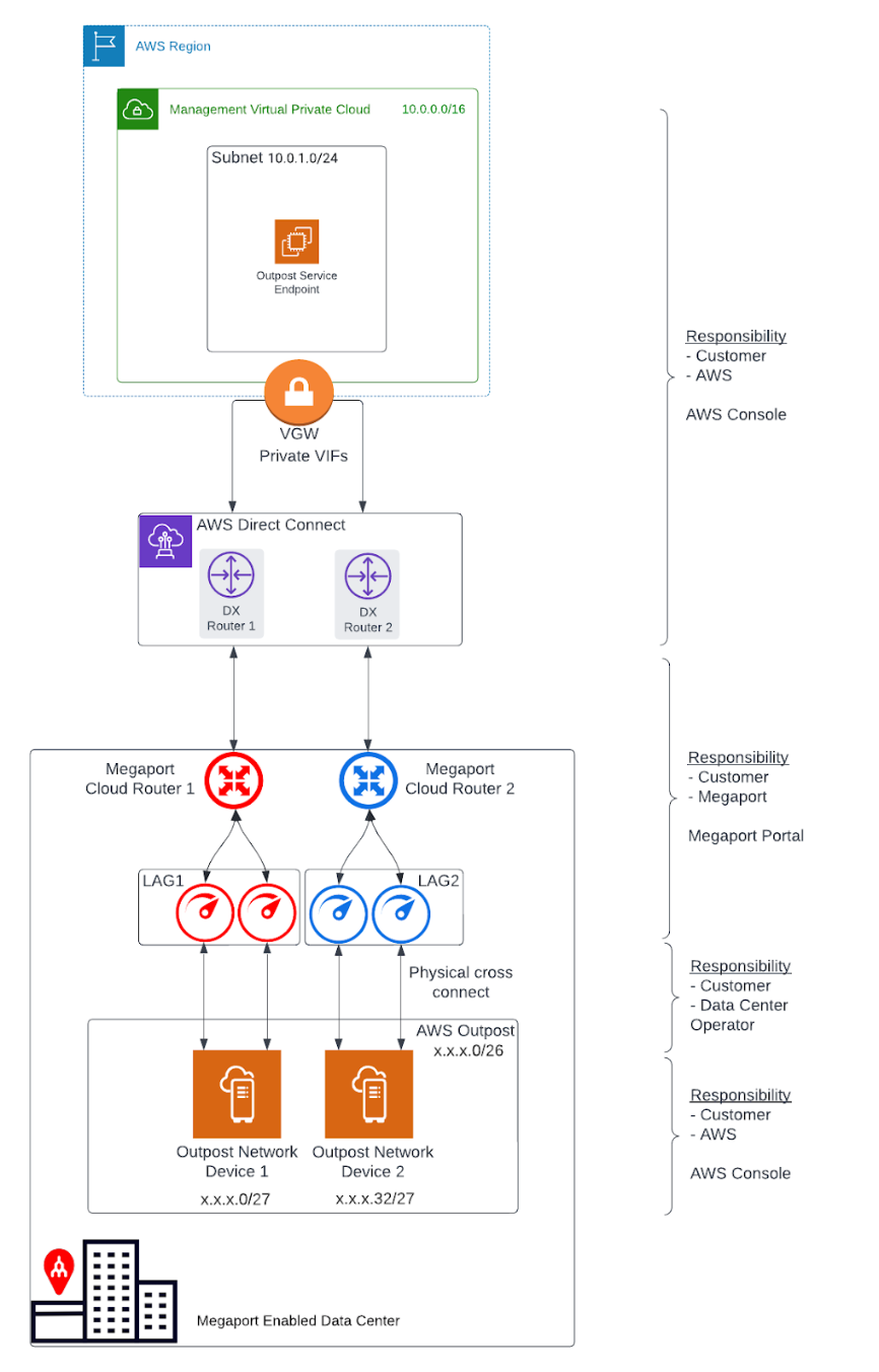
- An AWS Region and an on-premises network
- A VPC with multiple subnets in the Region
- A customer-owned IP address pool
- An Outpost in the on-premises network
- A Megaport MCR for routing between subnets
- A Megaport Port and VXC for AWS Region connectivity
- Physical fiber cross connects to Megaport
Redundancy
To establish full redundancy between each Outpost Rack Networking Device (OND) and Megaport, we recommend this configuration:
-
Each OND is dual connected to Megaport.
-
Two MCRs are configured for each Outpost deployment.
-
The Racks within the same Outpost deployment (second, third, and so on) use the same MCR pair; each OND for an additional Rack uses the same dual port and link aggregation group (LAG) configuration.
-
The MCRs terminate at different AWS Direct Connect locations.
VPCs and subnets
A VPC spans all Availability Zones in its AWS Region. You can extend any VPC in the Region to your Outpost by adding an Outpost subnet. To add an Outpost subnet to a VPC, specify the Amazon Resource Name (ARN) of the Outpost when you create the subnet. For more information, see Creating the Outpost subnet in this topic.
Outposts support multiple subnets. You can specify the EC2 instance subnet when you launch the EC2 instance in your Outpost. You cannot specify the underlying hardware where the instance is deployed, because the Outpost is a pool of AWS compute and storage capacity.
Each Outpost can support multiple VPCs that can have one or more Outpost subnets. For information about VPC quotas, see Amazon VPC Quotas in the Amazon Virtual Private Cloud User Guide. You create Outpost subnets from the VPC CIDR range of the VPC where you created the Outpost. You can use the Outpost address ranges for resources, such as EC2 instances that reside in the Outpost subnet. AWS does not directly advertise the VPC CIDR, or the Outpost subnet range to your on-premises location.
Outpost service link
The connection from an Outpost back to an AWS Region is called a service link. When you select the private connectivity option for your Outpost Region connectivity, AWS establishes the service link connection using the VPC and subnet that you specified.
For an optimal experience and resiliency, AWS recommends that you use redundant connectivity. The service link connection requires a minimum 500 Mbps or greater bandwidth connection. Your bandwidth requirements will vary, depending on:
-
The number of Outpost Racks and Outpost capacity configurations.
-
The workload characteristics, such as the Amazon Machine Image (AMI) size, application elasticity, burst speed requirements, and the Amazon VPC traffic to the Region.
Communication paths
You need to consider communication paths for two purposes:
-
The connection from an Outpost back to an AWS Region, called a service link path - To establish this path, you specify a VLAN subnet with a range of /30 or /31 and an IP address for the service link VLAN on the OND.
-
The connection from your on-premises network to a VPC, called a local gateway path - To establish this path, you specify a VLAN subnet with a range of /30 or /31 and an IP address for the local gateway VLAN on the OND.
Important
This topic covers only the service link path and doesn’t include the local gateway path details. For more information about the local gateway, see Local gateway network parameters in this topic, and Local gateway in the Outposts User Guide for Rack.
Service link networking parameters
The service link requires a /26 IPv4 address block advertised as two contiguous /27 blocks within your network. These IP blocks can be an RFC 1918 address space used on your local network, or another range of IPs you use privately. Alternatively, you can provide a /26 that is publicly addressable.
/26 IPv4 address block
These OND networking parameters configure the OND end of the LAG connection and the corresponding endpoints on MCR(s). For each MCR, you need:
- A service link BGP autonomous system number (ASN). The ASNs can be the same on each MCR.
- A VLAN that represents the point-to-point connectivity between the MCR and the ONDs.
- An IP address and subnet mask for each MCR (for a total of 2).
Each OND needs a service link BGP ASN and an IP address and subnet mask (for a total of 2). The MCR and Outpost BGP ASNs must be different.
Before you begin, define the networking parameters for the service link connection in this table:
| Component | Networking Parameters |
|---|---|
| Service link BGP ASN | 16 or 32-bit ASN from private ASN range (64512 - 65534 or 4200000000 - 4294967294) |
| First LAG (between the OND and MCR #1) | Outpost IP address and subnet mask (/30 or /31) |
| Customer IP address and subnet mask (/30 or /31) | |
| Customer BGP ASN (16 or 32-bit) | |
| Service Link VLAN1 (can be the same across LAGs) | |
| Second LAG (between the OND and MCR #2) | Outpost IP address and subnet mask (/30 or /31) |
| Customer IP address and subnet mask (/30 or /31) | |
| Customer BGP ASN (16 or 32-bit) | |
| Service link VLAN1 (can be the same across LAGs) |
Local gateway networking parameters
Important
This topic covers only the service link path and does not detail the local gateway path configuration. For more information about local gateways, see Local gateway in the Outposts User Guide for Rack.
A local gateway serves two purposes:
-
It provides a target in your VPC route tables for on-premises destined traffic.
-
It performs network address translation (NAT) for instances that have been assigned addresses from your customer-owned IP pool.
You can also use the local gateway for communication for internet-bound traffic.
You have several different options for local gateway connectivity via the Megaport MCR, depending on your current-state network and objectives.
A local gateway VLAN from the Megaport LAG Ports might have VLANs configured for one of these options:
- You might only use the service link path for region communication instead of using the local gateway.
- An Outpost data center LAN via a separate Megaport Port.
- A local AWS Region via an MCR.
- Any AWS Region via the Megaport network.
- Any Megaport-enabled data center globally.
The networking parameters for the local gateway will depend on the current state network and solution requirements.
Before you order
Ordering an Outpost is a two-step process: first, you order an Outpost from AWS. After installation of your Outpost, you create an Outpost subnet and link it with a VPC.
Before ordering an Outpost:
-
Make sure your site meets these detailed physical requirements: Site requirements for Outpost Rack.
-
You need an AWS Enterprise Support plan.
Ordering an Outpost
With the site requirements verified and an AWS support plan in place, follow these steps to order your Outpost.
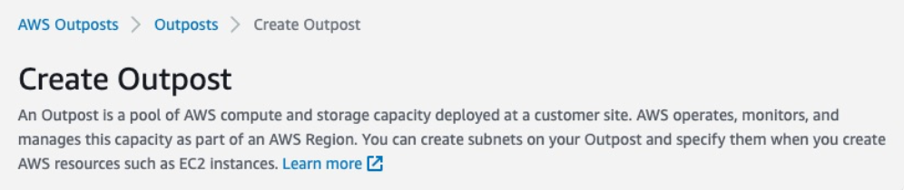
To order an Outpost
-
Open the AWS Outposts console.
-
Select Create Outpost.
-
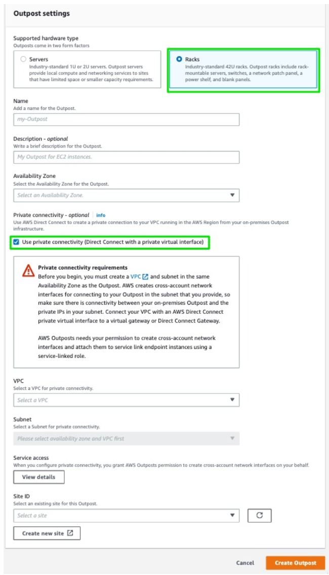
Select the Racks radio button.
-
Enter the name and description fields for your deployment.
-
Select an Availability Zone for your Outpost from the drop-down list.
-
Select the Use private connectivity check box.
Once you select the private connectivity option for your Outpost, AWS automatically creates a private connectivity endpoint and assigns private IPs to it from the VPC subnet’s CIDR that you have selected to use for the AWS Outpost private connectivity.
From then on:
-
All service link traffic between your AWS Outpost Rack and the AWS Outpost service endpoints in the Region will use your designated private connectivity.
-
AWS Outpost automatically creates a service-linked role in your account that enables it to complete the following tasks on your behalf:
-
Create network interfaces in the subnet and VPC that you specify, and creates a security group for the network interfaces.
-
Grant permission to the AWS Outpost service to attach the network interfaces to a service link endpoint instance in the account.
-
Attach the network interfaces to the service link endpoint instances from the account.
-
-
-
For VPC and Subnet, select a VPC and subnet in the same AWS account and Availability Zone as your Outpost.
-
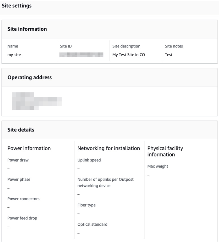
For Site ID, either click Create a new site, or select an existing site from the drop-down list. The site settings appear.
-
Click Create Outpost.
-
Choose the Outposts catalog from the menu on the left.
-
Select Supported hardware type, and choose a Configuration.
If an appropriate configuration option is not available, contact the AWS Outpost team to request a custom configuration.
-
Click Place order.
-
Choose Next.
-
Confirm your configuration, then click Place order.
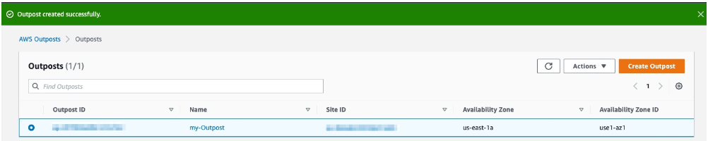
A dialog confirms that the Outpost order has been created and scheduled. Once you receive confirmation that the Outpost has been installed, the next step is to launch the instance on your Outpost Rack.
Before you launch an instance
Once your Outpost order is installed and available for use, you can launch your EC2 instance on your Outpost Rack. Before launching an instance, make sure you meet these prerequisites:
-
Configure permissions for an IAM entity (user or role) to allow the user or role to create the service-linked role for private connectivity. The IAM entity needs permission to access the following actions:
iam:CreateServiceLinkedRole on arn:aws:iam::*:role/aws-service-role/ outposts.amazonaws.com/AWSServiceRoleForOutposts*
iam:PutRolePolicy on arn:aws:iam::*:role/aws-service-role/ outposts.amazonaws.com/AWSServiceRoleForOutposts*
ec2:DescribeVpcs
ec2:DescribeSubnets -
In the same AWS account and Availability Zone as your Outpost, create a VPC for the sole purpose of Outpost private connectivity with a subnet /25 or larger that does not conflict with 10.1.0.0/16. (This block is defined and used by AWS for intra-VPC connectivity, including subnets in the Region.)
-
Enable a Megaport AWS Direct Connect (DX) transport between the data center Outpost location and the AWS Region with a Private VIF connection into the VPC.
-
Create an AWS Direct Connect connection, private virtual interface, and virtual private gateway to allow your Outpost to access the VPC.
-
Advertise the subnet CIDR to your on-premises network via AWS Direct Connect. For more information, see Direct Connect virtual interfaces and Working with AWS Direct Connect gateways.
Creating the Outpost subnet
After meeting the prerequisites, you need to create the Outpost subnet.
Once you create an Outpost subnet and link it with a VPC in the associated AWS Region, the VPC will cover the Outpost itself as well.
To create the Outpost subnet
- Open the AWS Outposts console.
- Select Outposts from the left navigation pane.
- Select the installed Outpost.
- Choose Actions, and then click Create Subnet.
- Select your VPC and determine an IP range for the subnet that you can allocate.
- Select Create.
AWS establishes the service link connection using the VPC and subnet that you specified. After the service link is established, the Outpost is in service and the AWS configuration is complete.
Megaport configuration
Now you are ready to set up the Megaport side of the Outposts deployment. The configuration steps are summarized here, with links to the procedure details:
- Create a Megaport Port.
- Create one or two MCRs and VXC connections.
- Create an AWS Direct Connect Hosted Connection.
- Accept the connection in the AWS Portal.
- Create the VIF in the AWS Portal.
- Create a private VXC between the Port and MCR to connect to an MCR in the current company account. A private VXC is essentially a point-to-point Ethernet connection between an A-End (your Port) and a B-End (the Private VXC destination type), which is the MCR in this case. Select the target MCR as the B-End of the connection.
Outposts Rack to Megaport Ports physical connection
The standard redundant deployment consists of four physical ports, connected to the Outposts Rack via fiber cross connects, as shown here:
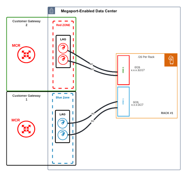
Configuration notes:
- Each OND connects to two physical Ports via a fiber cross connect.
- Each OND connects to separate zones (either Red or Blue) for physical redundancy.
- Each Port must be configured and deployed in a LAG group using the Link Aggregation Control Protocol (LACP). Ports in the red diversity zone are part of a LAG group. Ports in the blue diversity zone in a separate LAG group.
- Ports must be deployed at 10 Gbps.
- Creating the port generates a Letter of Authorization (LOA) for the port assignment on the Megaport network, as described in Creating a Port. This LOA is used by the data center operator to connect the fiber facilities. For more information about the terminating port specifications, see Technical Specifications.
- For diversity, each red and blue diversity zone is homed to a separate MCR.
- The LAG Ports and the MCR do not have to be in the same data center. They can be in separate locations and virtually connect across the Megaport network.
Creating a Port
The Megaport Portal steps you through selecting the data center location, specifying the Port details, and placing the order.
Note
Before proceeding, ensure that you have set up your Megaport Portal account. For more information, see Setting Up a Megaport Account.
To create a Port
-
In the Megaport Portal, go to the Services page.
-
Click Add Services, then select Port.

-
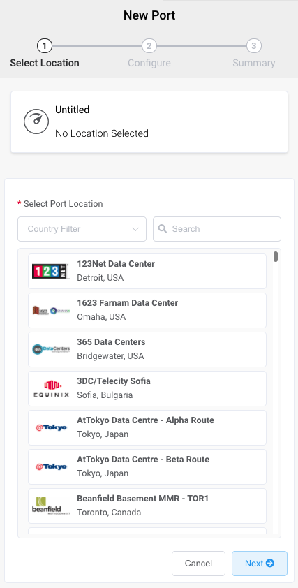
Select the data center where your Outposts Rack is deployed and click Next.
You can use the Search field to find the Port name, Country, Metro City, or address of your destination Port.
-
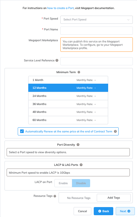
Specify the details for the Port.
-
Port Speed – Select 10 Gbps, or higher, from the Port Speed drop-down list.
-
Port Name – Specify a name for the Port that is easily identifiable.
-
Megaport Marketplace – By default, each service is private to your enterprise and consumes services from the Megaport network for your own internal company, team, and resources. When set to private, the service is not searchable in the Megaport Marketplace, however, others can still connect to you using a service key. Megaport Marketplace visibility is controlled on your Megaport Marketplace profile. For more information about how to make your service visible to the Megaport Marketplace, see Adding services to your profile.
-
Service Level Reference (optional) – Specify a unique identifying number for your Megaport service to be used for billing purposes, such as a cost center number, unique customer ID, or purchase order number. The service level reference number appears for each service under the Product section of the invoice. You can also edit this field for an existing service.
Note
A VXC associated with the Port is not automatically updated with the Port service level reference number.
-
Minimum Term – Select No Minimum Term, 12 Months, 24 Months, 36 Months, 48 Months, or 60 Months. Longer terms result in a lower monthly rate. 12 Months is selected by default. Take note of the information on the screen to avoid early termination fees (ETF).
Enable the Minimum Term Renewal option for services with a 12, 24, 36, 48 or 60-month term to automatically renew the contract at the same discounted price and term length at the end of the contract. If you don’t renew the contract, at the end of the term, the contract will automatically roll over to month-to-month contract for the following billing period, at the same price, without term discounts.
Note
Partner and Partner-managed accounts cannot view or change Port contract terms.
-
Cross Connect – When you have entered a Port speed, the Cross ConnectA Cross Connect is a dedicated physical point-to-point connection that links two parties within a data center. It is a non-standard product and can only be ordered with a Port.
section will appear if Cross Connect is available at your chosen location. Select Yes if you want to include a Cross Connect with your Port order. The price for the Cross Connect will be shown. For more information, see Ordering a Cross Connect. -
Port Diversity – Select a diversity option from the drop-down list. You can create two diverse Ports or choose an existing Port for the new Port to be diverse from. For more information about configuring Port diversity, see Port Diversity.
-
LACP on Port – The Outposts Rack solution requires that ports be enabled with LACP. Click Enable for the Port to be a member of a LAG.
Note
To enable LACP, the Port speed must be 10 Gbps or higher. Specify the number of Ports to include in the LAG, up to a maximum of 8. For more information about LAG, see Creating a Link Aggregation Group.
-
Resource Tags – You can use resource tags to add your own reference metadata to a Megaport service.
To add a tag:- Click Add Tags.
- Click Add New Tag.
- Enter details into the fields:
- Key – string maximum length 128. Valid values are a-z 0-9 _ : . / \ -
- Value – string maximum length 256. Valid values are a-z A-Z 0-9 _ : . @ / + \ - (space)
- Click Save.
If you already have resource tags for that service, you can manage them by clicking Manage Tags.
Warning
Never include sensitive information in a resource tag. Sensitive information includes commands that return existing tag definitions and information that will identify a person or company.
The price updates dynamically based on your selections. Note that some Partner-managed accounts do not display the pricing details.
-
-
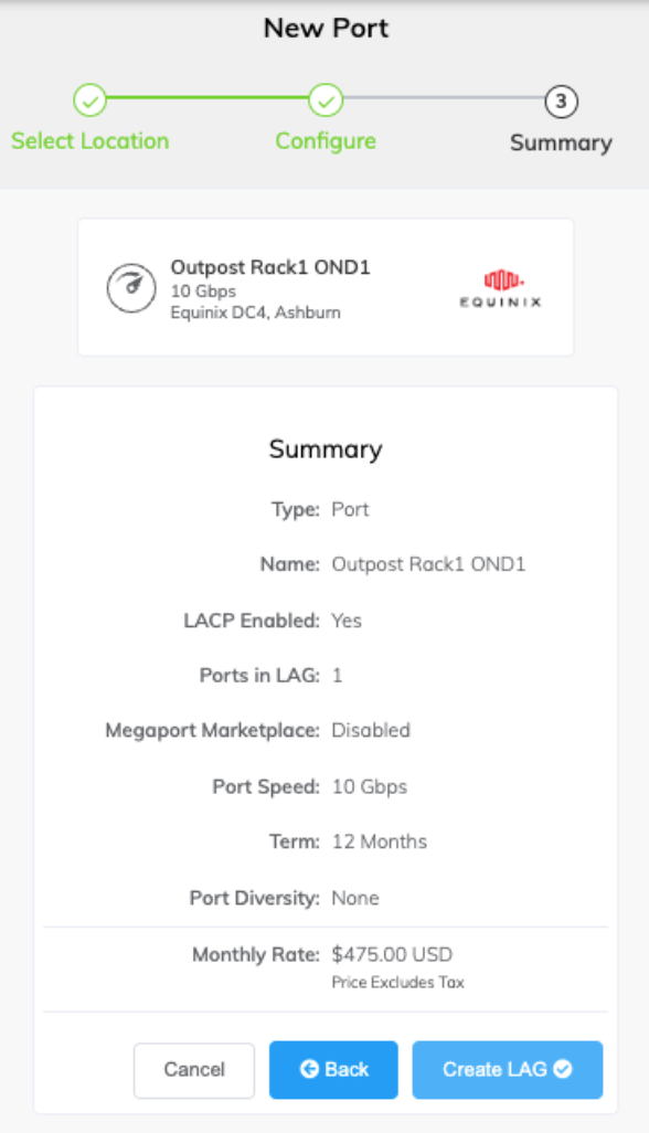
Click Next to view the Summary page. The monthly charges will be itemized on this page.
-
Confirm the selected options and click Create LAG.
The newly created Port(s) and their monthly charges appear under Configured Services, ready for you to add a connection. If you create a service in a market that is not enabled, you are prompted to enable it first.
-
Click Review Order to deploy the new Port(s) now, or click Save to save the configured services before placing the order.
-
Click Create Port to add more Ports in other locations.
-
Click Order Now to start the provisioning of your new Port.
In most cases the Port is provisioned immediately, but on occasion it can take longer. After the Port is provisioned, Megaport generates a Letter of Authorization (LOA) specifying the demarcation point to be applied to your service. A PDF of the LOA is sent to you by email.
-
Click the Download LOA link next to the new Port on the Services page. The Download LOA link appears once the Port is available.
-
Provide the LOA to your data center operator to establish the physical cross connect from your network device to your new Port.
Note
The cost of a new cross connection and any related VXC fees are the responsibility of the customer, as outlined in Megaport’s Global Services Agreement.
Creating an MCR
This section describes how to create a Megaport Cloud Router (MCR). The Megaport Portal steps you through selecting a location, specifying MCR configuration details, and placing the order.
Before you begin, you need to set up your portal account. You will only be able to create MCR instances in billing markets you are registered in. For more information, see Setting Up a Megaport Account.
To create an MCR
-
In the Megaport Portal, go to the Services page.
-
Click Add Services, then select MCR.
-
An MCR is physically homed to a Megaport core location. Select the preferred data center location for the MCR and click Next. The country you choose must be a market in which you have already registered.
Note
You can use the Search field to find the Port name, Country, Metro City, or address of your destination Port.
-
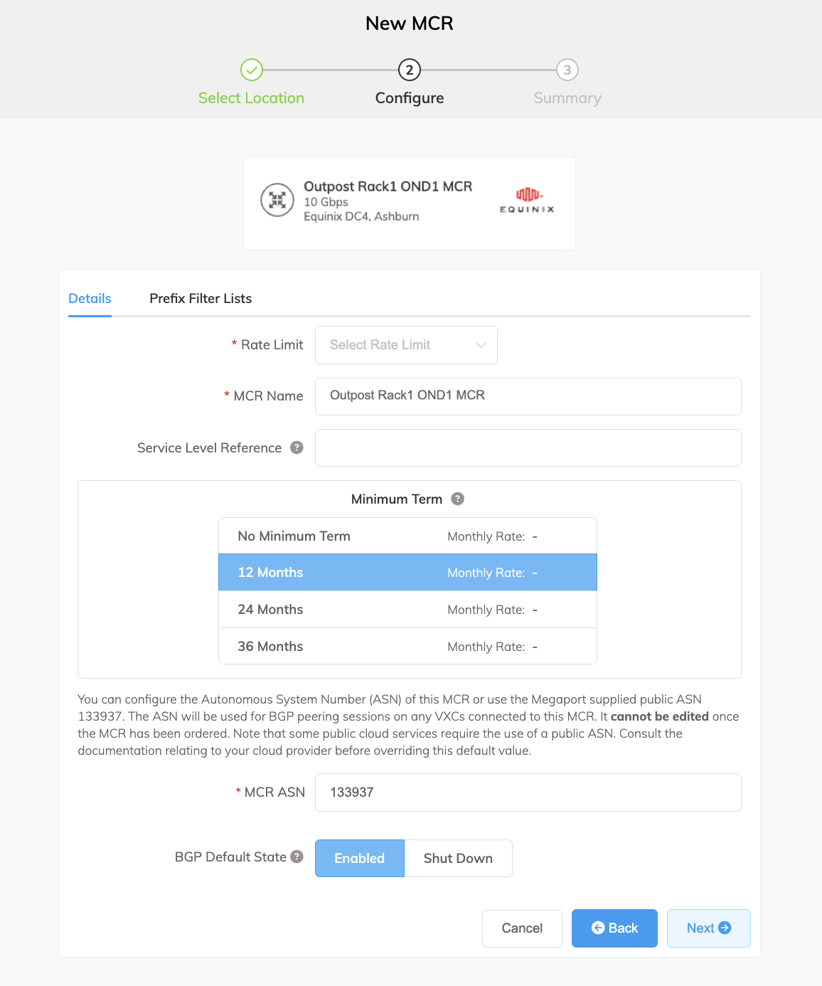
Specify the details for the MCR.
-
Rate Limit – Select a rate limit from the drop-down list. The MCR can scale from 1 Gbps to several Gbps, with higher speeds available in some regions. The rate limit is an aggregate capacity that determines the speed for all connections through the MCR. MCR bandwidth is shared between all the Cloud Service Provider (CSP) connections added to it. The rate limit is fixed for the life of the service.
-
MCR Name – Specify a name for the MCR that is easily identifiable, particularly when you are provisioning more than one MCR. You can change the name later, if you like.
-
Service Level Reference (optional) – Specify a unique identifying number for your Megaport service to be used for billing purposes, such as a cost center number, unique customer ID, or purchase order number. The service level reference number appears for each service under the Product section of the invoice. You can also edit this field for an existing service.
Note
A VXC associated with the MCR is not automatically updated with the MCR service level reference number.
-
Minimum Term – Select No Minimum Term, 12 Months, 24 Months, 36 Months, 48 Months, or 60 Months. Longer terms result in a lower monthly rate. 12 Months is selected by default. Take note of the information on the screen to avoid early termination fees (ETF).
Enable the Minimum Term Renewal option for services with a 12, 24, 36, 48 or 60-month term to automatically renew the contract at the same discounted price and term length at the end of the contract. If you don’t renew the contract, at the end of the term, the contract will automatically roll over to month-to-month contract for the following billing period, at the same price, without term discounts.
For more information about contract terms, see MCR Pricing and Contract Terms.
-
MCR ASN – Specify the autonomous system number (ASN) of this MCR, or use the default public ASN, 133937, supplied by Megaport. For most configurations, the default ASN is appropriate. The ASN is used for BGP peering sessions on any VXCs connected to this MCR.
-
BGP Default State – Select whether BGP connections are enabled or shut down by default.
Select Enabled (the default) if you want any new BGP sessions you configure to be live as soon as you save the configuration. Select Shut Down if you want any new BGP sessions you configure to be left in a shut down state when you save the configuration.
For example, you might want to select Shut Down if you are planning to add several BGP sessions across your Virtual Cross Connects (VXCs) but know that you want to do some other router setup before you want them exchanging route information. When you are finished configuring your routers, you can then go into the relevant BGP sessions and enable them.
You can override this setting for an individual connection in the BGP setup screen. For more information about overriding the BGP state for an individual connection, see Shutting down a BGP connection.
-
Resource Tags – You can use resource tags to add your own reference metadata to a Megaport service.
To add a tag:- Click Add Tags.
- Click Add New Tag.
- Enter details into the fields:
- Key – string maximum length 128. Valid values are a-z 0-9 _ : . / \ -
- Value – string maximum length 256. Valid values are a-z A-Z 0-9 _ : . @ / + \ - (space)
- Click Save.
If you already have resource tags for that service, you can manage them by clicking Manage Tags.
Warning
Never include sensitive information in a resource tag. Sensitive information includes commands that return existing tag definitions and information that will identify a person or company.
-
-
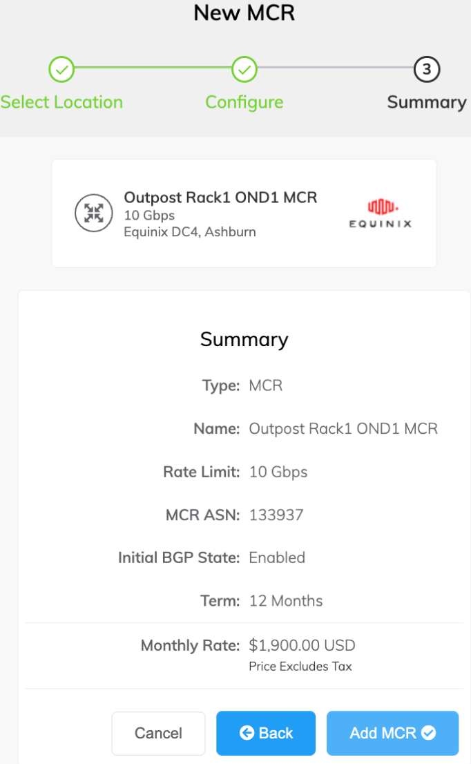
Click Next to view the Summary page.
The monthly rate is based on location and rate limit. (Note, some partner-managed accounts do not display the pricing details.)
-
Confirm the selected options and click Add MCR.
-
Click Create MCR to add more MCRs in other locations.
-
Click Review Order.
-
Review the Order Services agreement and click Order Now.
- Click Save to save the configured MCR before placing the order.
- Click Add Promo Code to enter a promotional code, and click Add Code.
The MCR provisioning takes approximately 59 seconds to complete.
Note
MCR is postpaid, so if you place your order on the 15th of January, your first invoice will be on the 1st of February, and the charge will reflect the 15th of January to the 31st of January.
Now that you’ve deployed an MCR, the next step is to add a Virtual Cross Connect (VXC) to AWS Direct Connect.
Creating MCR connections to AWS
You can create a VXC from an MCR to AWS Direct Connect (DX) through the Megaport Portal. Follow the steps in this section to establish a private VIF connection that can connect either directly to a selected VPC or to a range of VPCs either in a single or multiple AWS regions (within a single AWS account).
Before you begin
Note
AWS does not support AWS Transit Gateway for AWS Outposts private connectivity; the Amazon Direct Connect gateway is supported for cross-region Direct Connect access if required. Throughout this article, termination to an AWS VGW via a Private Virtual Interface (VIF) will be the default and recommended configuration.
Private Virtual Interface
Before you create a private connection from an MCR to AWS, make sure you have the following:
- Your AWS account number.
- An AWS virtual private gateway or Direct Connect gateway associated with your VPCs.
- The ASN number for the AWS gateway. When creating the AWS gateway, we recommend private ASNs for private connections and we recommend replacing the AWS default ASN (usually 7224) as routing multiple VXC instances to the same target ASN can result in routing anomalies.
Connecting a VXC from MCR to AWS Direct Connect
Once you have met the prerequisites, you can create the VXC to AWS from the MCR.
Note
As a best practice, we recommend that you use the AWS Hosted Connection Direct Connect model. This section focuses on the AWS Hosted Connections model for Direct Connect service delivery.
The Hosted Connection configuration process does not have automatic access to routing information for the MCR and you need to configure the routing manually and specify BGP peering details on both the AWS virtual interface and the MCR A-End configuration in the Megaport Portal.
Creating an AWS Direct Connect Hosted Connection
To create a Hosted Connection VXC from an MCR to AWS
-
In the Megaport Portal, go to the Services page and select the MCR you want to use.
-
Click +Connection and click Cloud.
-
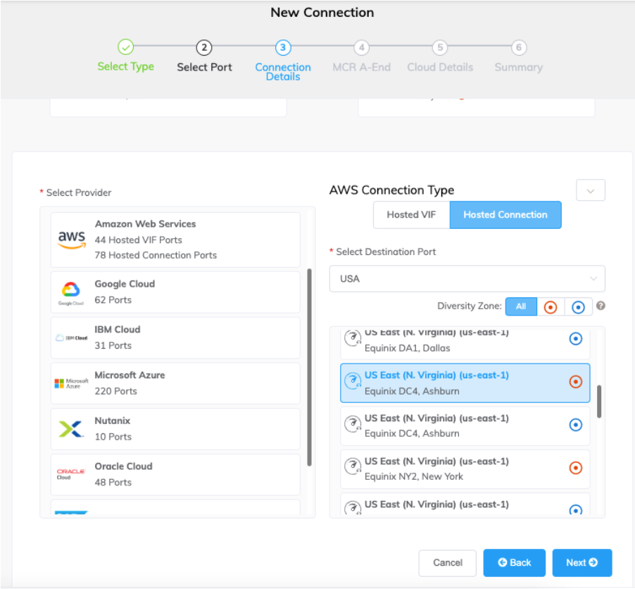
Select AWS as the service provider, select Hosted Connection as the AWS Connection Type, select the destination port, then click Next.
Each destination port has either a blue or a red icon to indicate its diversity zone. To achieve diversity, you need to create two connections with each one in a different zone.
You can use the Select Destination Port search field to narrow the selection and you can filter by diversity zone.
-
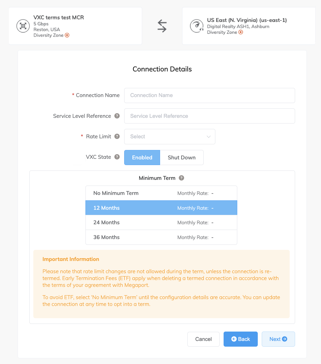
Specify the connection details:
-
Connection Name – The name of your VXC to be shown in the Megaport Portal.
-
Service Level Reference (optional) – Specify a unique identifying number for your Megaport service to be used for billing purposes, such as a cost center number, unique customer ID, or purchase order number. The service level reference number appears for each service under the Product section of the invoice. You can also edit this field for an existing service.
-
Rate Limit – The speed of your connection in Mbps. You must choose from the provided bandwidth options (50 Mbps to 25 Gbps). The sum of all hosted virtual VXCs to a service can exceed the Port capacity (for example, 10 Gbps, 100 Gbps, or higher), however the total aggregate will never burst beyond the Port capacity.
Note
The minimum supported rate limit for Outpost Rack VXCs is 500 Mbps.
-
VXC State – Select Enabled or Shut Down to define the initial state of the connection. For more information, see Shutting Down a VXC for Failover Testing.
Note
If you select Shut Down, traffic will not flow through this service and it will behave as if it was down on the Megaport network. Billing for this service will remain active and you will still be charged for this connection.
-
Minimum Term – Select No Minimum Term, 12 Months, 24 Months, 36 Months, 48 Months, or 60 Months. Longer terms result in a lower monthly rate. 12 Months is selected by default. Take note of the information on the screen to avoid early termination fees (ETF).
Enable the Minimum Term Renewal option for services with a 12, 24, 36, 48 or 60-month term to automatically renew the contract at the same discounted price and term length at the end of the contract. If you don’t renew the contract, at the end of the term, the contract will automatically roll over to month-to-month contract for the following billing period, at the same price, without term discounts.
For more information, see VXC Pricing and Contract Terms and VXC, Megaport Internet, and IX Billing.
-
Resource Tags – You can use resource tags to add your own reference metadata to a Megaport service.
To add a tag:- Click Add Tags.
- Click Add New Tag.
- Enter details into the fields:
- Key – string maximum length 128. Valid values are a-z 0-9 _ : . / \ -
- Value – string maximum length 256. Valid values are a-z A-Z 0-9 _ : . @ / + \ - (space)
- Click Save.
If you already have resource tags for that service, you can manage them by clicking Manage Tags.
Warning
Never include sensitive information in a resource tag. Sensitive information includes commands that return existing tag definitions and information that will identify a person or company.
-
-
Click Next.
-
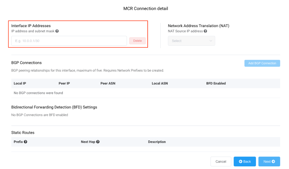
For the MCR Connection detail, provide an IP address in CIDR format.
This value is the IP address for the interface and is the MCR IP address used for BGP peering to AWS. Assign a /30 address in private address space.
You can add a secondary IP address, if needed.
Note
You can change these values in the A-End details of the VXC configuration.
-
Click Add BGP Connection.
-
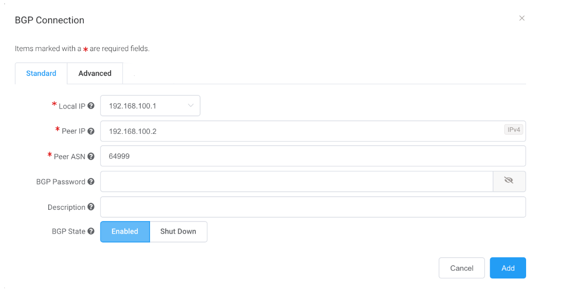
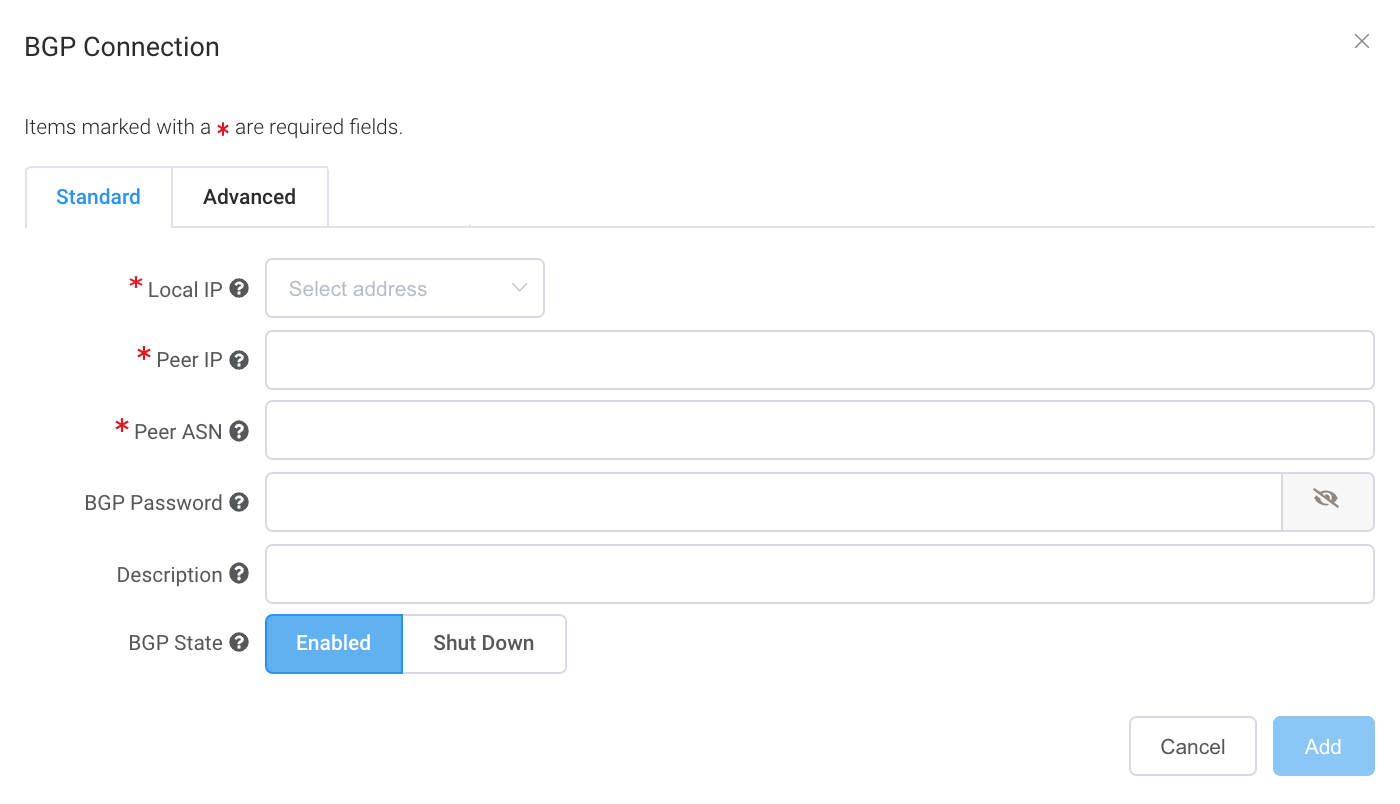
Specify these values:
-
Local IP – The IP address on this interface that communicates with the BGP peer.
The menu is automatically populated based on the address you specified as interface IP addresses.
-
Peer IP – The IP address for the BGP peer.
In this example, the local IP is 192.168.100.1 so the peer IP address would be 192.168.100.2. - Peer ASN – The ASN of the AWS gateway.
-
BGP Password – The shared key to authenticate the peer.
This field is optional for the creation of the VXC, but is required to set up the BGP peering. You can add it after you create the VXC.
The shared key length is from 1 to 25 characters. The key can include any of these characters:
a-z
A-Z
0-9
! @ # . $ % ^ & * + = - _ -
Description (optional) – Enter a description that will help identify this connection.
The minimum description length is from 1 to 100 characters. -
BGP State – Shuts down the connection without removing it.
The initial setting will be taken from the setting on the A-End of the MCR. Enabling or shutting down the BGP state does not affect existing BGP sessions. The BGP state only affects new VXCs. This setting overrides the MCR state for an individual connection. For more information, see Creating an MCR.
When you create the virtual interface in the AWS console for this connection, you will match these values.
-
-
Click Add.
The BGP details appear under BGP Connection details. -
Click Next.
-
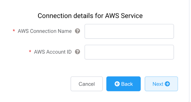
Specify the connection details for the AWS service.
-
AWS Connection Name – This is a text field and will be the name of your virtual interface that appears in the AWS console. The AWS Connection Name is automatically populated with the name specified in a previous step.
-
AWS Account ID – This is the ID of the account you want to connect. You can find this value in the management section of your AWS console.
-
-
Click Next to proceed to the connection detail summary, click Add VXC, and order the connection.
After the VXC connection is deployed successfully, it appears on the Megaport Portal Services page and is associated with the MCR. Click the VXC title to display the details of this connection.
Note that the service status (Layer 2) is up but BGP (Layer 3) will be down because the configuration does not exist yet.
After the connection is deployed in the Megaport Portal, you need to accept the connection in the AWS console.
Accepting the connection
To accept the connection
-
In AWS, go to Services > AWS Direct Connect > Connections and click the connection name to review the details and accept. For more information, see the AWS documentation.
The state will be pending for a few minutes while AWS deploys the connection.
Creating the VIF
To create the virtual interface
-
In the AWS console, click Create Virtual Interface. Enter these values for BGP peering:
- Your router peer IP – The BGP peer IP configured on the MCR.
- Amazon router peer IP – The BGP peer IP configured on the AWS endpoint.
- BGP authentication key – The password used to authenticate the BGP session.
Important
-
AWS provides detailed steps for creating a Private Virtual Interface.
-
The name you provided for the connection in the Megaport Portal appears in the Connection list on this page.
-
The VLAN is populated and appears to be editable; however, you will get an error if you try to change it.
After you accept the Hosted Connection in AWS and create a virtual interface with the BGP peering settings, the VXC state changes to configured in the Megaport Portal.
Creating a private VXC between a Port and an MCR
This section describes how to connect a private Virtual Cross Connect (VXC) between a Port and the Megaport Cloud Router in the Megaport network.
With a Port configured, you can deploy a private VXC to connect to an MCR in the current company account. A private VXC is essentially a point-to-point Ethernet connection between an A-End (your Port) and a B-End (the Private VXC destination type) which is the MCR in this case.
To deploy a private VXC
-
In the Megaport Portal, go to the Services page and select the Port you want to use.
-
Select the originating Port (the A-End).
-
Click +Connection.
-
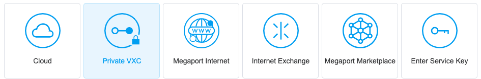
Click Private VXC.
-
Select the target MCR (the B-End).
-
Click Next.
-
Specify the connection details:
-
Connection Name – The name of your VXC to be shown in the Megaport Portal. Specify a name for the VXC that is easily identifiable. You can change the name later, if you like.
-
Service Level Reference (optional) – Specify a unique identifying number for your Megaport service to be used for billing purposes, such as a cost center number, unique customer ID, or purchase order number. The service level reference number appears for each service under the Product section of the invoice. You can also edit this field for an existing service.
-
Rate Limit – The speed of your connection in Mbps. The maximum speed is displayed, and is set by the lowest speed at each end.
-
VXC State – Select Enabled or Shut Down to define the initial state of the connection. For more information, see Shutting Down a VXC for Failover Testing.
Note
If you select Shut Down, traffic will not flow through this service and it will behave as if it was down on the Megaport network. Billing for this service will remain active and you will still be charged for this connection.
-
Preferred A-End VLAN – Specify the 802.1q VLAN tag for this connection for the A-End. Each VXC is delivered as a separate VLAN on your Port. This must be a unique VLAN ID on this Port and can range from 2 to 4093. If you specify a VLAN ID that is already in use, the system displays the next available VLAN number. The VLAN ID must be unique to proceed with the order. If you don’t specify a value, Megaport will assign one. Leave the Port tag setting to Tagged.
-
Minimum Term – Select No Minimum Term, 12 Months, 24 Months, 36 Months, 48 Months, or 60 Months. Longer terms result in a lower monthly rate. 12 Months is selected by default. Take note of the information on the screen to avoid early termination fees (ETF).
Enable the Minimum Term Renewal option for services with a 12, 24, 36, 48 or 60-month term to automatically renew the contract at the same discounted price and term length at the end of the contract. If you don’t renew the contract, at the end of the term, the contract will automatically roll over to month-to-month contract for the following billing period, at the same price, without term discounts.
For more information, see VXC Pricing and Contract Terms and VXC, Megaport Internet, and IX Billing.
-
Resource Tags – You can use resource tags to add your own reference metadata to a Megaport service.
To add a tag:- Click Add Tags.
- Click Add New Tag.
- Enter details into the fields:
- Key – string maximum length 128. Valid values are a-z 0-9 _ : . / \ -
- Value – string maximum length 256. Valid values are a-z A-Z 0-9 _ : . @ / + \ - (space)
- Click Save.
If you already have resource tags for that service, you can manage them by clicking Manage Tags.
Warning
Never include sensitive information in a resource tag. Sensitive information includes commands that return existing tag definitions and information that will identify a person or company.
-
-
Click Next.
The next step is to configure the BGP settings for this VXC. For each VXC connected to an MCR you can configure one or more interfaces, IP addresses, BGP connections, or static routes. Most VXCs will use one interface. In this case, you specify one interface and add one BGP connection.
To configure the BGP settings for the VXC
-
On the MCR Connection details page, click Add BGP Connection.
-
Select the Local IP on this interface that communicates with the BGP peer from the drop-down menu.
-
Specify the BGP details for the Peer IP, Peer ASN, where the peer settings are related to the OND.
-
Click Add to save the VXC.
Repeat these steps to configure more VXCs. -
Click Next.
-
Click Review Order to proceed through the ordering process.
When the VXCs are deployed, you can view them in the Portal Services page. Note that the service identifier number is the same for the VXCs at both ends of the connection.
Verifying the BGP configuration
The MCR Looking Glass provides single-screen visibility into the BGP configuration. For more information, see Viewing Traffic Routing Through MCR Looking Glass.
To view the BGP status
- In the Megaport Portal, go to the Services page.
- Select the VXC.
- Click MCR A-End or MCR B-End.
- Choose Details.
Troubleshooting BGP
If the Services > Connection Detail page displays a status issue, verify these items:
- Select the VXC and select MCR A-End or B-End.
- Under BGP Connections, verify that the correct local ASN is in use for the A-End of the VXC.
- Verify that the correct peer IP address is in use.
- Verify that the correct BGP MD5 password is in use for the A-End of the VXC.
If the BGP configuration looks correct:
-
Make sure that a BGP peer is not blocking ingress or egress from TCP port 179 (BGP) and other relevant ephemeral ports.
-
Verify that a BGP peer is not advertising more than 100 prefixes to AWS. The maximum number of advertised routes to AWS is 100. The BGP session is disabled if it exceeds the prefix limit of 100 advertised routes.
Shutting down a BGP connection
Use this setting to temporarily disable the BGP session without removing it. BGP shutdown provides a way to administratively shut down a BGP connection while setting up a new route, performing maintenance, troubleshooting, and so on.
To temporarily disable a BGP connection
- In the Megaport Portal, go to the Services page.
- Select the VXC and select the A-End or B-End.
- After the BGP connection details, click Shut Down.
- Click Yes to confirm.