Creating an MCR VXC
With a Megaport Cloud Router (MCR) configured, you can add a Virtual Cross Connect (VXC) to a CSP, a local port, or a third-party network. You can optionally connect a physical Port to the MCR via a private VXC or connect to a service provider in the Megaport Marketplace.
A VXC is a point-to-point Layer 2 circuit between two endpoints that is mapped with a VLAN ID on each end. You can order VXCs to reach any destination in the Megaport network just like the VXCs used with the physical Ports. You can connect up to 25 VXCs per MCR.
Note
The VXC target destination type determines the peering type. The peering type determines which routes are advertised. For more information, see MCR Route Advertisement.
- Log in to the Megaport Portal, select
Services, then select the MCR.
If you haven’t already created an MCR, see Creating an MCR. -
If this is the first connection for the MCR, click the tile that matches the VXC type. The tile is a shortcut to the configuration page.
Alternatively, click +Connection and select a destination type: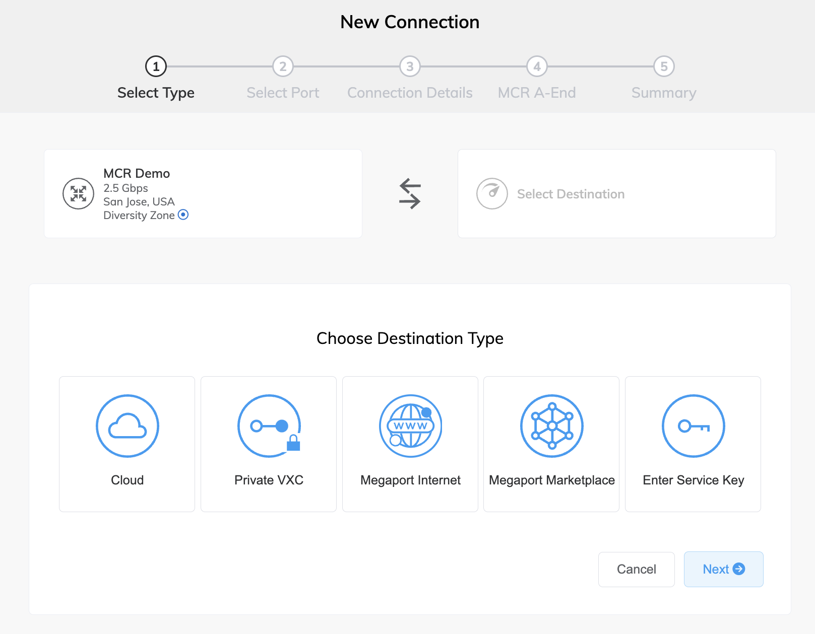
-
Cloud – Provision a dedicated interconnect to a public cloud service provider. After selecting Cloud, select a provider. Some providers require a service key.
For specific CSP configuration details:
- 3DS Outscale – See Creating MCR Connections to 3DS Outscale.
- Alibaba – See Creating MCR Connections to Alibaba Express.
- AWS – See Creating MCR Connections to AWS.
- Azure – See Creating MCR Connections to Azure using ExpressRoute.
- DigitalOcean – See Creating MCR Connections to DigitalOcean Infrastructure.
- Google – See Creating MCR Connections to Google Cloud Services.
- IBM – See Creating MCR Connections to IBM Cloud Direct Link.
- Oracle – See Creating MCR Connections to Oracle Cloud Infrastructure.
- OVHcloud – See Creating MCR Connections to OVHcloud Connect.
- Salesforce – See Creating MCR Connections to Salesforce Express Connect.
- SAP – See Creating MCR Connections to SAP HANA Enterprise Cloud.
-
Private VXC – Connect to other Ports local to the current company account. After selecting Private VXC, select a destination Port. For more information, see Creating a Private VXC.
- Megaport Internet – Connect to the internet. After selecting Megaport Internet, select a destination Port (internet router). For more information, see Creating a Megaport Internet Connection for an MCR.
- Megaport Marketplace – Connect to any service provider present in the Megaport Marketplace. After selecting Megaport Marketplace, select a provider. For more information, see Megaport Marketplace.
- Enter Service Key – Connect to a third-party on the Megaport network that isn’t publicly listed in the Megaport Marketplace. Select this destination if you have been given a service key, and enter the service key. For more information, see Creating a Connection using a Service Key.
-
-
Click Next.
-
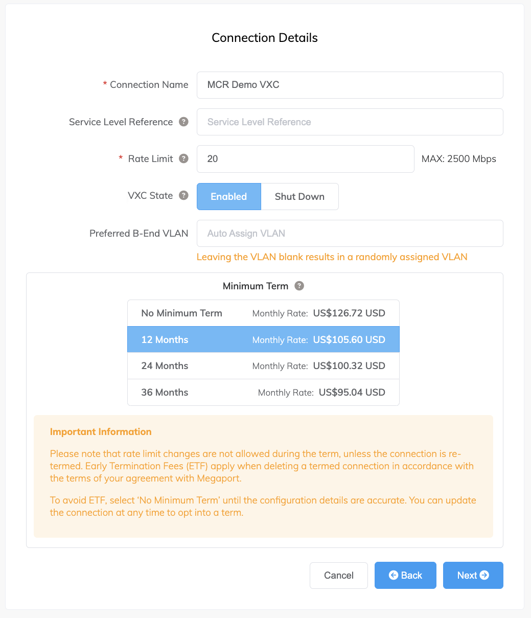
Specify the connection details:
-
Connection Name – The name of your VXC to be shown in the Megaport Portal.
-
Service Level Reference (optional) – Specify a unique identifying number for your Megaport service to be used for billing purposes, such as a cost center number, unique customer ID, or purchase order number. The service level reference number appears for each service under the Product section of the invoice. You can also edit this field for an existing service.
-
Rate Limit – The speed of your connection in Mbps. Specify a rate limit that doesn’t exceed the total rate limit for the MCR. Allow enough bandwidth for any connections that you might add later.
-
VXC State – Select Enabled or Shut Down to define the initial state of the connection. For more information, see Shutting Down a VXC for Failover Testing.
Note
If you select Shut Down, traffic will not flow through this service and it will behave as if it was down on the Megaport network. Billing for this service will remain active and you will still be charged for this connection.
-
Preferred B-End VLAN – Specify the 802.1q VLAN tag for this connection that you will receive through the B-End VLAN. This field will show if the configuration requires this information.
-
Minimum Term – Select No Minimum Term, 12 Months, 24 Months, 36 Months, 48 Months, or 60 Months. Longer terms result in a lower monthly rate. 12 Months is selected by default. Take note of the information on the screen to avoid early termination fees (ETF).
Enable the Minimum Term Renewal option for services with a 12, 24, 36, 48 or 60-month term to automatically renew the contract at the same discounted price and term length at the end of the contract. If you don’t renew the contract, at the end of the term, the contract will automatically roll over to month-to-month contract for the following billing period, at the same price, without term discounts.
For more information, see VXC Pricing and Contract Terms and VXC, Megaport Internet, and IX Billing.
-
Resource Tags – You can use resource tags to add your own reference metadata to a Megaport service.
To add a tag:- Click Add Tags.
- Click Add New Tag.
- Enter details into the fields:
- Key – string maximum length 128. Valid values are a-z 0-9 _ : . / \ -
- Value – string maximum length 256. Valid values are a-z A-Z 0-9 _ : . @ / + \ - (space)
- Click Save.
If you already have resource tags for that service, you can manage them by clicking Manage Tags.
Warning
Never include sensitive information in a resource tag. Sensitive information includes commands that return existing tag definitions and information that will identify a person or company.
-
-
Click Next.
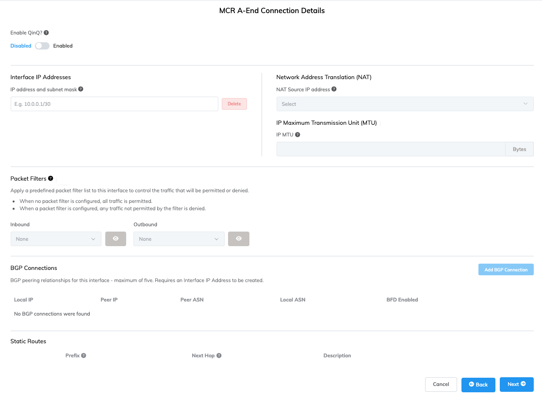
The MCR A-End Connection Details page appears. For each VXC connected to an MCR, you can configure one or more interfaces, IP addresses, BGP connections, packet filter lists, and static routes. Most VXCs will use one interface, however, you can configure multiple interfaces by enabling a Q-in-Q802.1Q tunneling (also known as Q-in-Q or 802.1ad) is a technique used by OSI Layer 2 providers for customers. 802.1ad provides for both an inner and an outer tag whereby the outer (sometimes called S-tag for service provider) can be removed to expose the inner (C-tag or customer) tags that segment the data.
connection and specifying an inner VLAN tag for each interface. Each VLAN ID must be unique and you can add up to five VLAN IDs.Note
The MCR A-End Connection Details page is not displayed during MCR VXC creation in some situations, and is dependent on the VXC destination. The MCR VXC configuration will be auto-configured in these situations. If you are creating a single-use service key on an MCR, the configuration is not auto-configured and the page will be displayed. For information about configuring connection details when they are auto-configured, see Configuring an MCR.
-
If required, click Enable Q-in-Q to enable multiple interfaces and click + Add Interface to add an additional interface.
-
Enter a description for the connection.
-
Enter one or more interface IP addresses and subnet masks to configure on the A-End interface.
-
(Optional) Select a NAT source IPv4 address from the Network Address Translation (NAT) drop-down list.
All packets leaving this interface will have their source NAT rewritten to this address.Network Address Translation (NAT)Network Address Translation (NAT) translates private, unregistered IP addresses used within an organization’s internal network into a single registered public IP address before sending packets to an external network. NAT enables private IP networks to access the internet and cloud services.
allows flexibility in designing a scalable and secure multi-vendor, multicloud, or hybrid cloud scenario. Source NAT translates the source IP address of a packet leaving the MCR. When you assign a NAT IP address in MCR, all packets leaving the interface use that IP address as their source IP address. Enable this feature when NAT is required for a connection, for example, when you need to translate several private IP addresses into a single public IP address to meet Cloud Service Provider (CSP) requirements.For more information about how MCR performs NAT to support public peering types to cloud service providers, see How MCR performs NAT.
-
(Optional) Enter an IP MTU (Maximum Transmission Unit)IP MTU (Maximum Transmission Unit) refers to the largest size (in bytes) of an IP packet that can be sent over a network interface (VXC). Jumbo packets are larger than the standard 1500 bytes (MTU), and are typically used in high-performance networks to reduce overhead and improve efficiency.
value (in bytes) for the VXC.
The IP MTU can range from 1280 to 9070 (9074 if Q-in-Q is disabled). The default value is 1500.
For more information, see MCR Advanced VLAN and Routing Features and Using IPsec with MCR. -
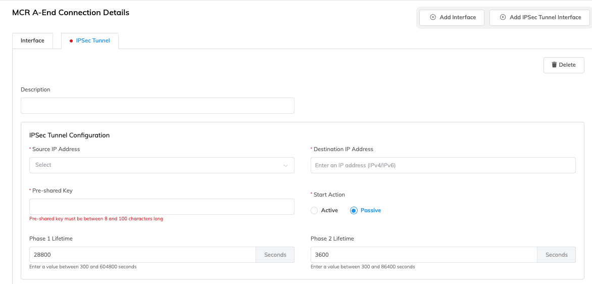
(Optional) If IPsec has been enabled on your MCR, you can configure IPsec tunnels.
Click + Add IPsec Tunnel Interface.
Add the IPsec tunnel details:- Description – Enter a description of the IPsec tunnel for your reference.
- Source IP Address – Click the box and select the address from the drop-down list.
This is a list of interface IP addresses defined on this VXC. - Destination IP Address – Add the destination IP address.
The destination IP address of the tunnel must not be an IP address configured on the same MCR. - Pre-shared key – Add a key that is common to both the IKE2 (Internet Key Exchange version 2) initiator and responder. The length must be between 8 and 100 characters.
- Local Identifier (optional) – Enter the identifier used for IKE authentication. This allows you to override the default source IP address with a non-IP address, which is required for some configurations. By default, the source IP address is used. Valid values include IPv4/IPv6 addresses, domain names, and email addresses (lowercase, 5-100 characters). For example,
megaport.comoruser@example.com. - Remote Identifier (optional) – Enter the identifier used for IKE authentication. This allows you to override the default destination IP address with a non-IP address, which is required for some configurations. By default, the destination IP address is used. Valid values include IPv4/IPv6 addresses, domain names, and email addresses (lowercase, 5-100 characters). For example,
megaport.comoruser@example.com. - Start Action – Select either active or passive. Passive indicates that the local MCR is an IPsec responder waiting for the remote to perform IKE2 initiation.
- Phase 1 Lifetime – Enter a value between 300 and 604800 seconds. This is the lifetime of IKE2 session in seconds. The default value is 28800 seconds (8 hours). When it expires, rekeying will occur.
- Phase 2 Lifetime – Enter a value between 300 and 86400 seconds. This is the lifetime in seconds of the IPsec Security Association (SA). The value must be less than the Phase 1 Lifetime. The default value is 3600 seconds (1 hour). When it expires, rekeying will occur.
-
Enter any details specific to the VXC type.
- For more information about configuring IPsec, see Using IPsec with MCR.
- For more information about using packet filters, see Using Packet Filters.
- For more information about adding a BGP connection, see Configuring BGP.
- For more information about enabling Bidirectional Forwarding Detection (BFD) settings, see Enabling the BFD protocol.
- For more information about adding a static route, see Configuring static routes.
-
Click Next.
-
Configure the B-End.
The requirements will vary by destination or provider. -
Click Next.
The Summary page appears.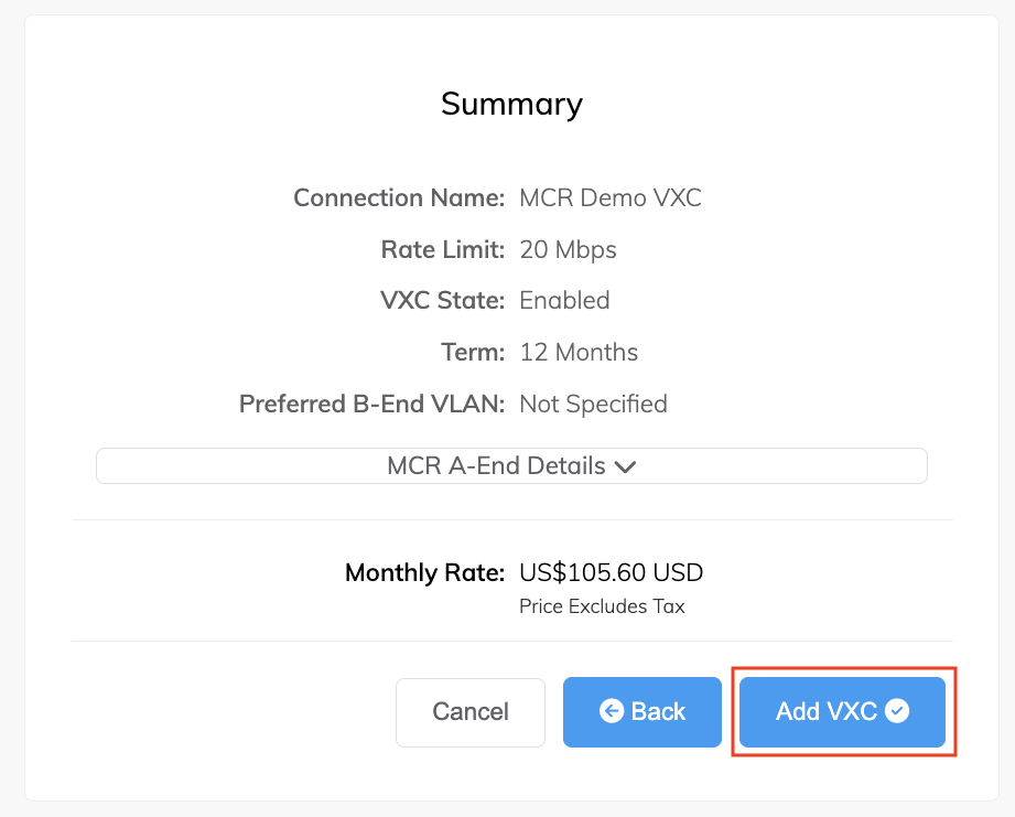
-
Review the Summary details.
Click each down arrow to view A-End and B-End configuration details. -
Click Add VXC to move this configuration to your cart.
-
Repeat these steps to provision any additional VXCs.
-
Click Review Order to proceed through the checkout process, or click Save to save the configured services before placing the order.
-
Review the Important Information section and confirm agreement with the Service Agreements.
If you do not have a promotion code, skip to the Order Now step. If you do have a promotion code, enter it into the Enter discount code field then click Apply. Alternatively, if a code already appears in the Discounts field, verify it is correct and click Apply.
The promotional discount appears below the Standard Term discount. This discount is not reflected in the Monthly Rate shown here, it is applied at the time of billing. If an invalid or expired code causes an error with your order, contact your Megaport Account Manager for a replacement code.
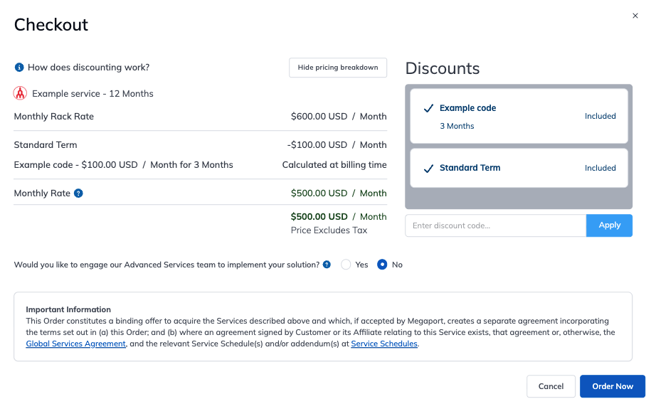
If you entered an incorrect promotion code, you can remove it by clicking Remove.
-
Click Order Now.