Creating an Azure Connection for an MVE with Palo Alto VM-Series
You can create a network connection from an MVE (a Palo Alto VM-Series firewall) to Azure ExpressRoute with Virtual Cross Connects (VXCs). You can create either a private connection or a public (Microsoft) connection.
Important
Before you begin, create an MVE (VM-Series). For more information, see Creating an MVE.
There are three parts to adding an ExpressRoute connection to your MVE and VM-Series.
-
Set up your ExpressRoute plan and deploy the ExpressRoute circuit in the Azure console. When deployed, you get a service key. For additional details, see the Microsoft ExpressRoute documentation.
-
In the Megaport Portal, create a connection (VXC) from your MVE to your ExpressRoute location.
-
In VM-Series, create a new interface and add the details of the ExpressRoute connection.
The instructions in this topic describe the second and third parts.
Note
MVE for Palo Alto requires configuration steps in both VM-Series and the Megaport Portal for all cloud connections.
Adding the ExpressRoute connection in the Megaport Portal
To set up the ExpressRoute connection, you need to create the connection in the Megaport Portal.
To create a connection to ExpressRoute from the Megaport Portal
-
In the Megaport Portal, go to the Services page and select the MVE you want to use.
-
Click +Connection on the MVE.

-
Click the Cloud tile.
-
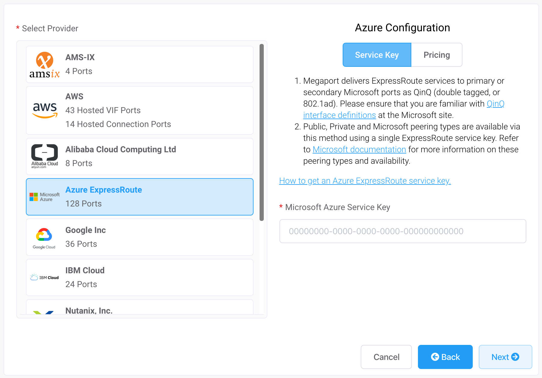
Select Azure ExpressRoute as the provider.
-
Add the ExpressRoute service key into the field in the right hand pane.
The Portal verifies the key and then displays the available port locations based on the ExpressRoute region. For example, if your ExpressRoute service is deployed in the Australia East region in Sydney, you can select the Sydney targets. -
Select the connection point for your first connection.
To deploy a second connection (and this is recommended), you can create a second VXC - enter the same service key and select the other connection target. Some helpful links appear on the configuration screen to resources including the Azure Resource Manager console and some tutorial videos. -
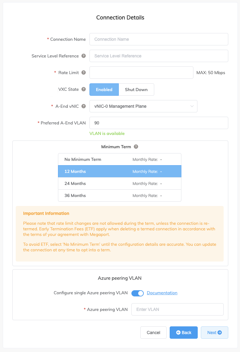
Specify the connection details:
-
Connection Name – The name of your VXC to be shown in the Megaport Portal.
-
Service Level Reference (optional) – Specify a unique identifying number for the VXC to be used for billing purposes, such as a cost center number or a unique customer ID. The service level reference number appears for each service under the Product section of the invoice. You can also edit this field for an existing service.
Note
Partner-managed accounts can apply a Partner Deal to a service. For more information, see Associating a Deal With a Service.
-
Rate Limit – The speed of your connection in Mbps. The rate limit for the VXC will be capped at the maximum allowable based on the ExpressRoute service key.
-
VXC State – Select Enabled or Shut Down to define the initial state of the connection. For more information, see Shutting Down a VXC for Failover Testing.
Note
If you select Shut Down, traffic will not flow through this service and it will behave as if it was down on the Megaport network. Billing for this service will remain active and you will still be charged for this connection.
-
A-End vNIC – Select an A-End vNIC from the drop-down list. See Creating an MVE in the Megaport Portal for more information about vNICs.
-
Preferred A-End VLAN – Specify an unused VLAN ID for this connection (for ExpressRoute this is the S-Tag). This must be a unique VLAN ID on this MVE and can range from 2 to 4093. If you specify a VLAN ID that is already in use, the system displays the next available VLAN number. The VLAN ID must be unique to proceed with the order. If you don’t specify a value, Megaport will assign one.
-
Minimum Term – Select No Minimum Term, 12 Months, 24 Months, or 36 Months. Longer terms result in a lower monthly rate. 12 Months is selected by default.
Take note of the information on the screen to avoid early termination fees (ETF). See VXC Pricing and Contract Terms and VXC, Megaport Internet, and IX Billing for more information. -
Configure Single Azure Peering VLAN – By default, this option is enabled for MVE and we strongly recommend keeping it enabled with Palo Alto VM-Series.
This option provides a single tag VLAN solution. You configure peering in Azure with the MVE VLAN (A-End) and the peer VLAN set in Azure (B-End). Note, you can have only one peering type (Private or Microsoft) per VXC with this option.Important
If you do not enable this option, the VXC appears active but it does not recognize traffic.
-
Azure Peering VLAN – This value needs to match the A-End VLAN for single tag VLAN peering. A different Azure peering VLAN can also be set, if required.
-
-
Click Next and proceed through the ordering process.
When the VXC configuration completes, the VXC icon is green.
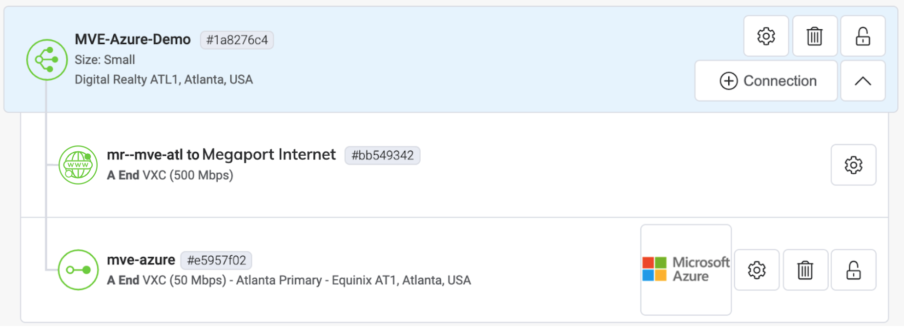
In the Azure Resource Management console, the provider status will be Provisioned.

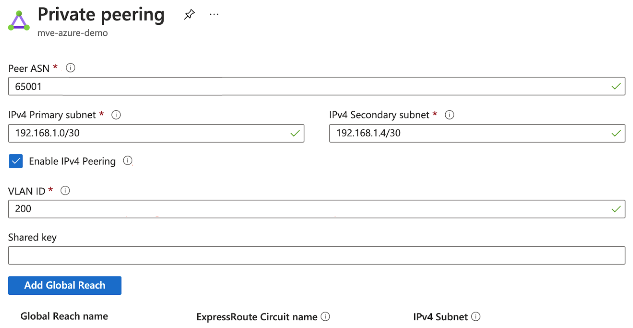
When provisioned, you need to configure peerings. You can configure private and Microsoft peering. Click the peer to configure and provide these details:
- Peer ASN – Enter the ASN for the MVE.
- IPv4 Subnets – From each of these subnets, MVE uses the first usable IP address and Microsoft uses the second usable IP for its router.
- VLAN ID – Enter the A-End VLAN from the MVE. (Note, the VLAN ID in the Azure console can be different from the A-End VLAN.)
- Shared Key (optional) – Enter an MD5 password for BGP.
Adding the ExpressRoute connection to VM-Series
After you create the connection from your MVE to Azure and set up the connection in the Azure console, you need to configure it in VM-Series. This involves creating an interface and configuring BGP settings, ASNs, VLANs, and MD5 values.
To add the Azure Cloud connection in VM-Series
-
Collect the connection details from the Azure console.
Display the details of the connection you created in Azure for this connection. Note the values for the Peer ASN, Shared Key, VLAN ID, and IPv4 Primary Subnet. -
Collect the connection details from the Megaport Portal.
Click the gear icon for the Azure connection from your MVE and click the Details view. Note the value for the A-End VLAN. -
Log in to the VM-Series.
-
Choose Network > Interfaces.
-
Select the A-End MVE (
ethernet1/1). -
Click Add Subinterface.
-
Provide these details:
-
Interface Name – Enter a name for the subinterface. In the adjacent field, enter a number to identify the subinterface.
-
Comment – Enter an alternate name.
-
Tag – Specify the A-End VLAN associated with this Azure Connection in the Megaport Portal.
-
Virtual Router – Select a virtual router to the interface, as required by your network.
-
-
Select the IPv4 tab.
- Select Static as the Type.
- Click +Add to add a new IP address.
- Enter the IPv4 address and netmask.
These values are available in the Azure console. The IP addresses and CIDR appear in the IPv4 Primary Subnet field; MVE uses the first usable IP address and Azure uses the second usable IP for its router. For this field, enter the MVE (first usable) IP address. - Click OK.
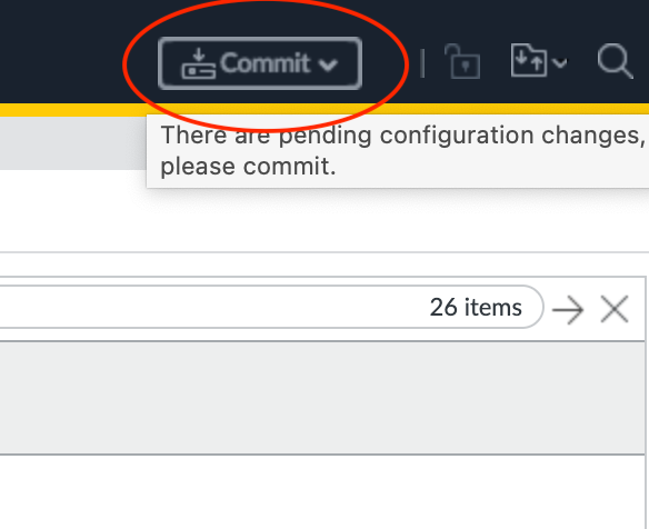
- Click Commit in the top right corner.
- Review the changes and click Commit.
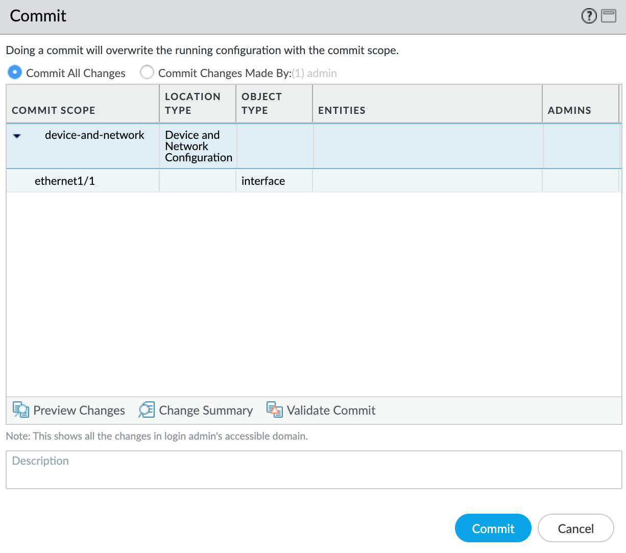
The new VLAN interface appears with your ethernet1/1 physical interface.
Next, you will create a security zone so the interface can route traffic.
To create a security zone
- Select the
ethernet1/1.1010subinterface. - Select New Zone from the Security Zone drop-down list.
- Specify a name for the security zone.
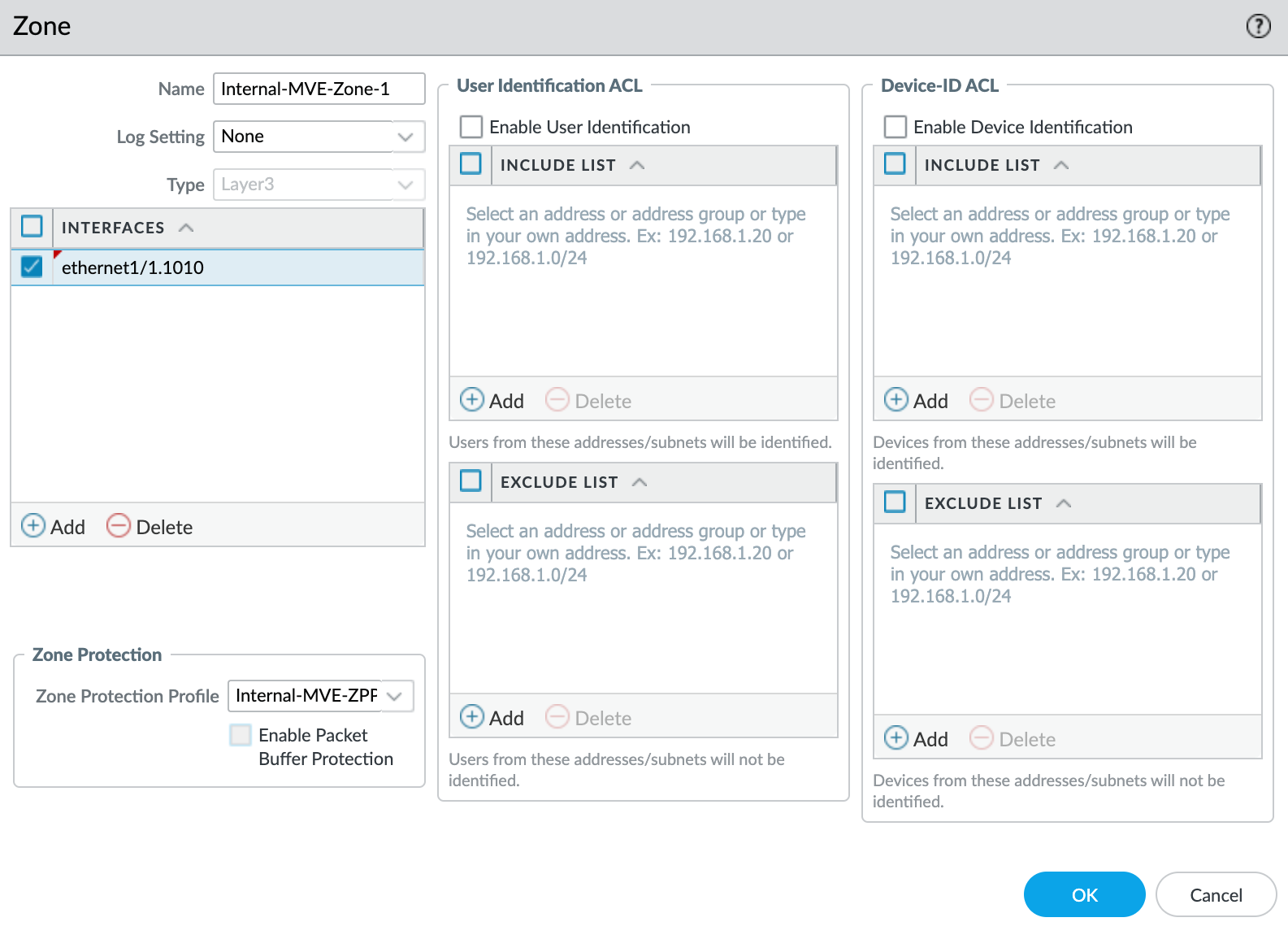
- Click +Add under Interfaces and add
ethernet1/1.1010to the security zone. - Specify any additional details as required for your network security.
- Select New Zone Protection Profile from the Zone Protection Profile drop-down list.
- Specify any details as required for your network security. This example uses all the defaults.
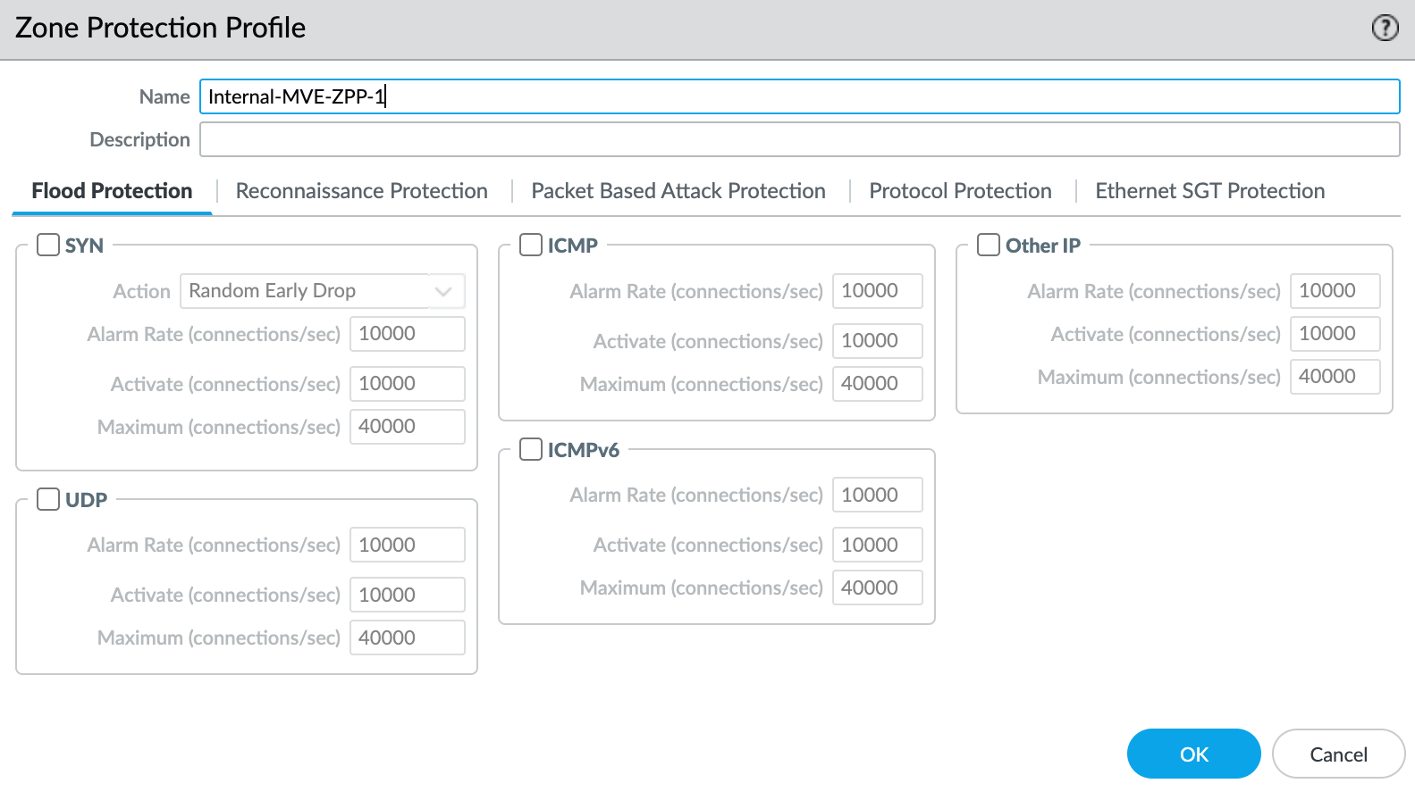
- Click OK.
- Click OK in the Layer3 Subinterface screen.
- Click Commit in the top right corner.

- Review the changes and click Commit.

At this point, you have created the interface. Next, you need to create the BGP session.
To create the BGP session
- In VM-Series, choose Network > Virtual Routers.
- Select the virtual router.

- In the left pane, select BGP.
-
Provide the following BGP details:
- Enable – Select this check box to start the BGP session after committing these changes.
- Router ID – Enter the first usable IP address from the IPv4 Primary Subnet from the Azure console.
- AS Number – Provide the ASN for the MVE connection. Provide the ASN for the MVE connection. Use the Peer ASN from the Azure console.
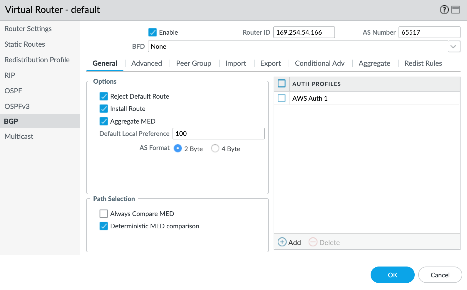
-
Click +Add under Auth Profiles.
- Specify a Profile Name.
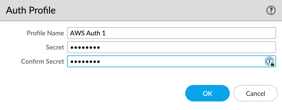
- Enter and confirm the auth password.
- Click OK.
- Select the Peer Group tab.
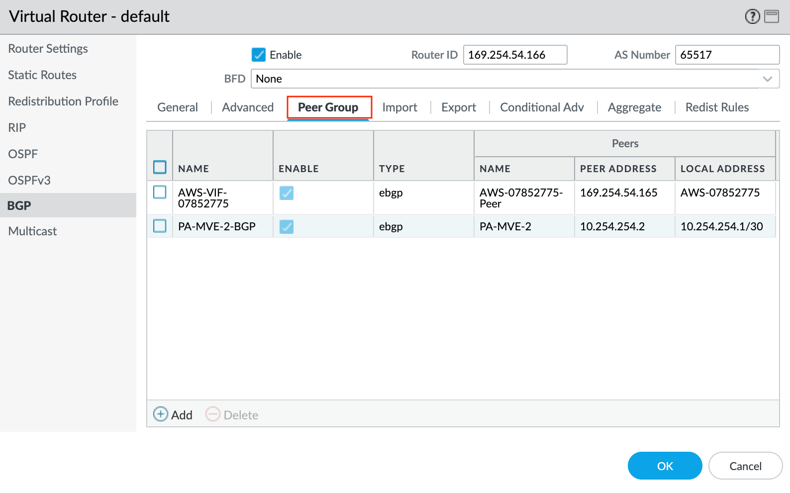
- Click +Add to add a peer group.
- Specify a name for the peer group. For example, AWS-xxxx.
- Specify eBGP as the session type.
- Specify any additional details as required for your network.
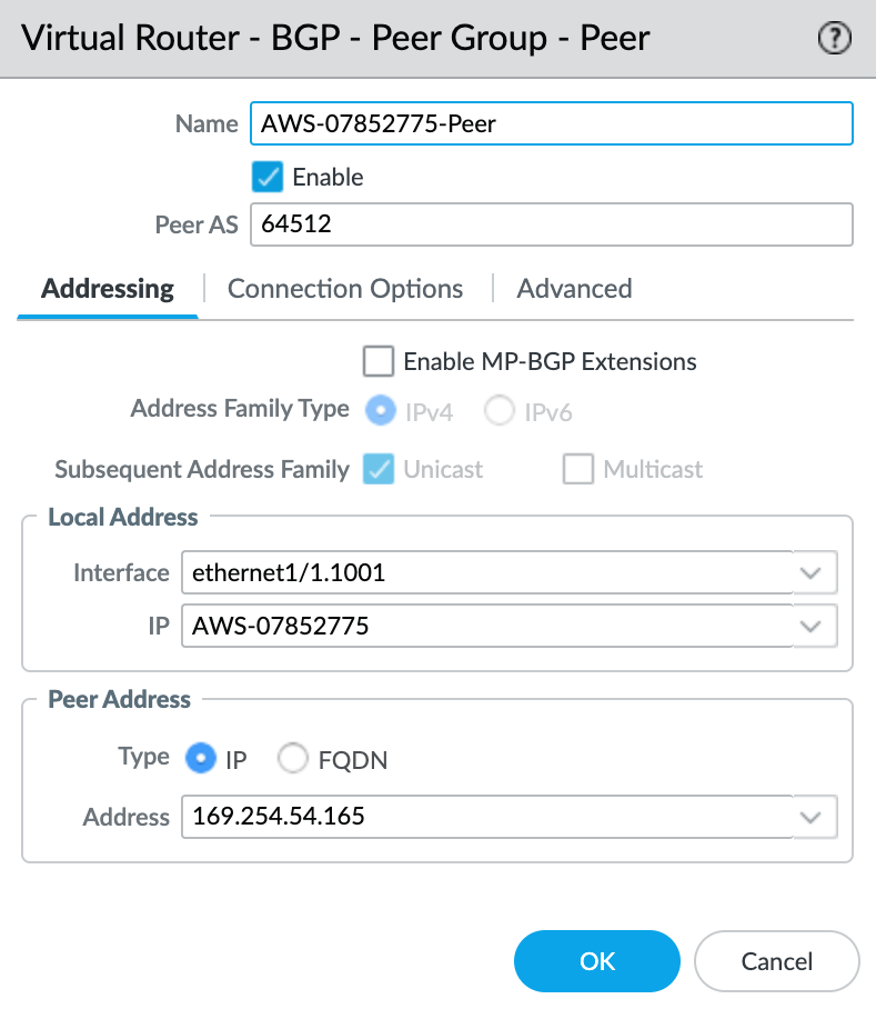
- Click +Add to add a new peer.
- Specify the details for the peer:
- Name – Specify a name for the peer.
- Peer AS – Specify the Azure-side ASN of 12076. This is a fixed value, and appears in the connection details on the Azure console.
- Local Address – Select the proper subinterface and IP address from the drop-down list.
- Peer Address – Enter the second usable IP address from the IPv4 Primary Subnet from the Azure console.
Validating your Azure connection
To check the status of the BGP peer
- Choose Network > Virtual Routers.
- Locate your virtual router (default).
- Click More Runtime Stats in the Runtime Stats column on the right.

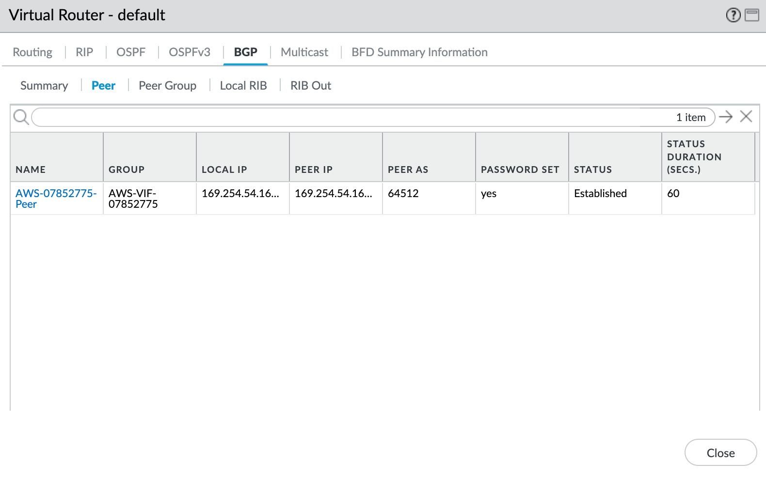
- Select the BGP tab, and then select the Peer tab.
- Verify that the peer status is Established.
