Creating MVE Connections to Any Endpoint with Cisco SD-WAN
This topic describes the general steps to configure and deploy a Megaport VXC connection in the Megaport Portal and integrate it with an MVE (the interconnect gateway) in Cisco SD-WAN. The VXC can connect to a Cloud Service Provider, a Port, or an MCR.
Tip
Although you can create MVE-to-MVE and AWS connections from the MVE in the Portal, Megaport strongly recommends creating these connections in vManage for seamless integration with your Cisco SD-WAN environment.
Step 1 – Create an MVE
- Create an MVE (Cisco interconnect gateway) in vManage.
For more information, see Creating an MVE. The MVE needs to be in the active state.
Step 2 – Create a VXC from the MVE
- In the Megaport Portal, select the MVE created in Step 1.
- Create a VXC to a Port, MCR, or Cloud Service Provider.
For more information, see Creating a VXC. - In the connection details, note the A-End VLAN.
Step 3 – Copy the default device template
- In Cisco vManage, go to Configuration > Templates and select the Device tab.
- Make a copy of Default_MEGAPORT_ICGW_C8000V_Template_V01.
Click the ellipsis (…) at the end of the row and select Copy from the drop-down list. - Provide a name for the copied template and click Copy.
This name can contain only uppercase and lowercase letters, the digits 0 through 9, hyphens, and underscores. It cannot contain spaces or any other characters.
Step 4 – Create a VPN feature template
- On the Templates page, select the Feature tab and click +Add Template.
- In Select Devices, select the C8000v.
- Under Select Template > VPN, click Cisco VPN.
- Enter a template name and description.
- In the Basic Configuration section, enter the VPN (VRF) ID for the VXC.
The VPN ID can be any number 1 – 511 or 513 – 65530. VPN 0 is reserved for Transport VPN and VPN 512 is reserved for Managed VPN. The number is normally identical to the VPN ID assigned for corporate networks to communicate between the corporate network and cloud service. - Click Save.
Step 5 – Create a BGP feature template
- On the Templates page, select the Feature tab and click +Add Template.
- In Select Devices, select the C8000v.
- In Select Template > OTHER TEMPLATES click Cisco BGP.
- Enter a template name and description.
- In the Neighbor section, click +New Neighbor.
-
Next to the Address field, select Device Specific from the drop-down list.
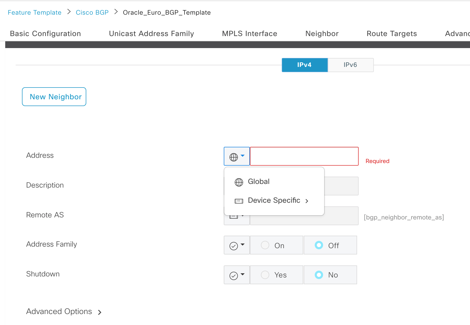
-
Next to the Remote AS field, select Device Specific from the drop-down list.
- Click Add and click Save.
Step 6 – Create a CLI add-on feature template
- On the Templates page, select the Feature tab and click +Add Template.
- In Select Devices, select the C8000v.
- In Select Template > OTHER TEMPLATES click Cli Add-On Template.
- Enter a template name and description.
-
Copy the following configuration into the CLI CONFIGURATION field.
-
Click Save.
Step 7 – Apply the feature templates to the device template
- Go to Configuration > Templates and select the Device tab.
- Select the MVE template that was copied from the default in Step 1.
- Click the ellipses (…) in the last column and choose Edit.
- In the Transport & Management VPN section, from the Cisco VPN 512 drop-down list, select Factory_Default_Cisco_VPN_512_Template.
- In Service VPN, click +Add VPN.
- Select the VPN template created in Step 4, click the arrow to move it to the Selected VPN Templates pane, and click Next.
The select sub-templates step appears. - In Additional Cisco VPN Templates, click Cisco BGP.
- From the Cisco BGP drop-down list, select the BGP template created in Step 5 and click Add.
- In Additional Templates, from the CLI Add-On Template drop-down list, select the CLI template created in Step 6.
- Click Update.
Step 8 – Apply the device template to MVE
- Go to Configuration > Templates and select the Device tab.
- Select the MVE template that was copied from the default in Step 1.
- Click the ellipses (…) in the last column and choose Attach Devices.
- Select the live MVE that was created before starting Step 1, move it to the right pane, and click Attach.
Next, enter device-specific information. -
Click the ellipses (…) in the last column and click Edit Device Template.
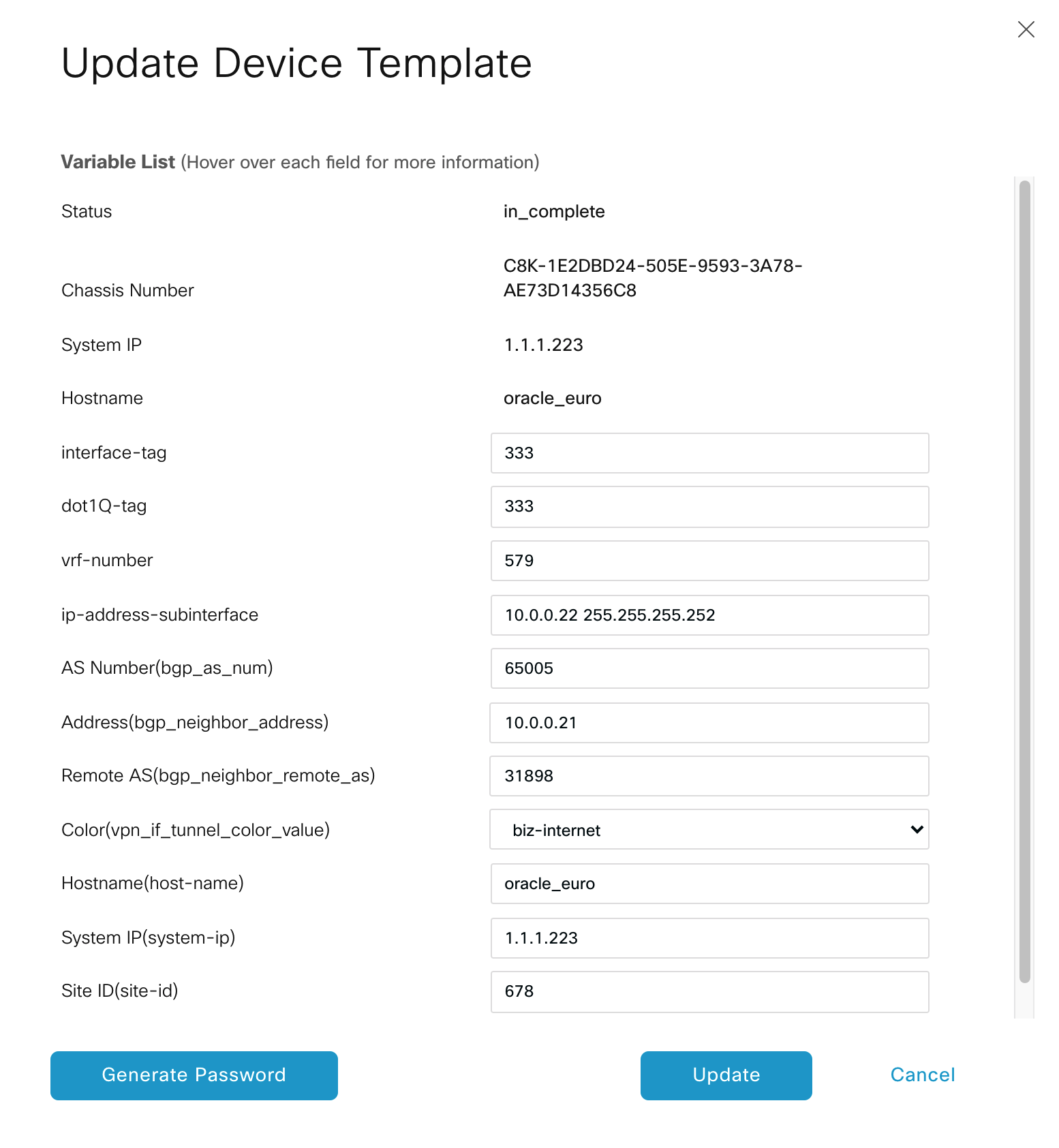
-
Enter values in these fields:
- interface-tag – This value is the same as dot-1Q-tag.
- dot-1Q-tag – This value is the same as interface-tag. You can find this value in the VXC connection details on the Megaport Portal: click the VXC name, click Details, and use the A-End VLAN value.
- vrf-number – Specify the VRF number (VPN ID) for the interface.
- ip-address-subinterface – Specify the IP address and mask of the interface.
- AS Number – Specify the AS number of the MVE.
- Address – Specify the remote BGP peer IP address.
- Remote AS - Enter the ASN for the remote BGP peer.
-
Click Update.
- Click Next.
vManage displays the Config Preview and Config Diff. Use these features to ensure the correct configuration will be applied. - Select the MVE on the left.
- Click Configure Devices.
vManage pushes the configuration to the MVE. When complete, the status indicates success.
Step 9 – Verify the connection
- In vManage, go to Tools > SSH Terminal.
- Select the MVE in the device group.
An SSH terminal opens. - Enter your login details.
-
Enter the following command to ping the other end of the Megaport VXC from the MVE.
ping vrf <VPN ID> <IP address> -
Enter the following command to confirm the BGP session is up:
show ip bgp vpnv4 vrf <VPN ID> summary