Creating an AWS Hosted Connection for an MVE with Versa Secure SD-WAN
A Hosted Connection can support one private, public, or transit virtual interface. These are dedicated connections and are recommended for production environments.
To create a Hosted Connection from an MVE to AWS
-
In the Megaport Portal, go to the Services page and select the MVE for the connection.
-
Click +Connection then click Cloud.
-
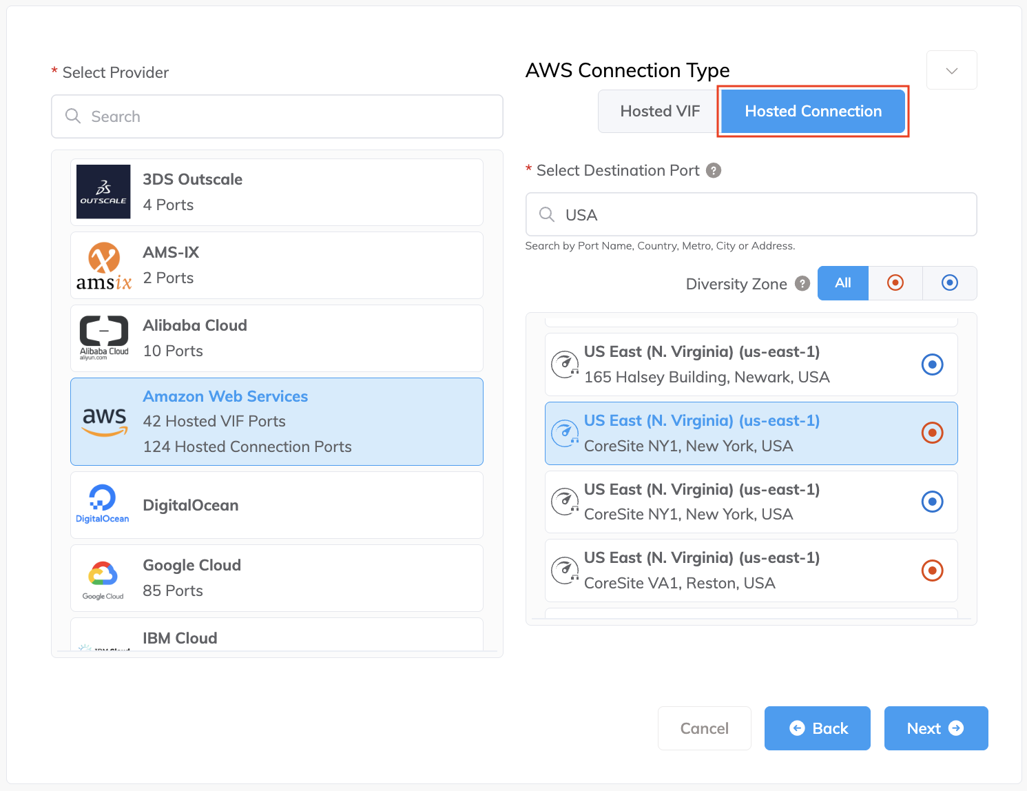
Select AWS as the service provider, select Hosted Connection as the AWS Connection Type, select the destination port, then click Next.
You can use the Select Destination Port search field to narrow the selection.
Each destination port has either a blue or red icon to indicate its diversity zone. To achieve diversity, you need to create two connections with each one in a different zone.
-
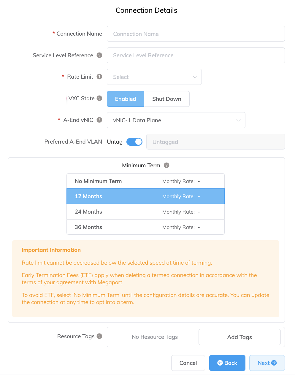
Specify the connection details:
-
Connection Name – The name of your VXC to be shown in the Megaport Portal.
-
Service Level Reference (optional) – Specify a unique identifying number for your Megaport service to be used for billing purposes, such as a cost center number, unique customer ID, or purchase order number. The service level reference number appears for each service under the Product section of the invoice. You can also edit this field for an existing service.
-
Rate Limit – The speed of your connection. This value cannot be changed after deployment. The drop-down list displays predefined rate limits available for your MVE, with speeds varying by location and service capabilities.
-
VXC State – Select Enabled or Shut Down to define the initial state of the connection. For more information, see Shutting Down a VXC for Failover Testing.
Note
If you select Shut Down, traffic will not flow through this service and it will behave as if it was down on the Megaport network. Billing for this service will remain active and you will still be charged for this connection.
-
A-End vNIC – Select an A-End vNIC from the drop-down list. For more information about vNICs, see Creating an MVE in the Megaport Portal.
-
Preferred A-End VLAN (optional) – Specify an unused VLAN ID for this connection.
This must be a unique VLAN ID on this MVE and can range from 2 to 4093. If you specify a VLAN ID that is already in use, the system displays the next available VLAN number. The VLAN ID must be unique to proceed with the order. If you don’t specify a value, Megaport will assign one. -
Minimum Term – Select No Minimum Term, 12 Months, 24 Months, 36 Months, 48 Months, or 60 Months. Longer terms result in a lower monthly rate. 12 Months is selected by default. Take note of the information on the screen to avoid early termination fees (ETF).
Enable the Minimum Term Renewal option for services with a 12, 24, 36, 48 or 60-month term to automatically renew the contract at the same discounted price and term length at the end of the contract. If you don’t renew the contract, at the end of the term, the contract will automatically roll over to month-to-month contract for the following billing period, at the same price, without term discounts.
For more information, see VXC Pricing and Contract Terms and VXC, Megaport Internet, and IX Billing.
-
Resource Tags – You can use resource tags to add your own reference metadata to a Megaport service.
To add a tag:- Click Add Tags.
- Click Add New Tag.
- Enter details into the fields:
- Key – string maximum length 128. Valid values are a-z 0-9 _ : . / \ -
- Value – string maximum length 256. Valid values are a-z A-Z 0-9 _ : . @ / + \ - (space)
- Click Save.
If you already have resource tags for that service, you can manage them by clicking Manage Tags.
Warning
Never include sensitive information in a resource tag. Sensitive information includes commands that return existing tag definitions and information that will identify a person or company.
-
-
Click Next.
-
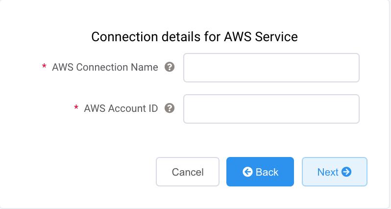
Specify the connection details for the AWS service.
-
AWS Connection Name – This is a text field and will be the name of your virtual interface that appears in the AWS console. The AWS Connection Name is automatically populated with the name specified in a previous step.
-
AWS Account ID – This is the ID of the account you want to connect. You can find this value in the management section of your AWS console.
-
-
Click Next to proceed to the connection detail summary, then click Add VXC.
-
Click Review Order to proceed through the checkout process, or click Save to save the configured services before placing the order.
-
Review the Important Information section and confirm agreement with the Service Agreements.
If you do not have a promotion code, skip to the Order Now step. If you do have a promotion code, enter it into the Enter discount code field then click Apply. Alternatively, if a code already appears in the Discounts field, verify it is correct and click Apply.
The promotional discount appears below the Standard Term discount. This discount is not reflected in the Monthly Rate shown here, it is applied at the time of billing. If an invalid or expired code causes an error with your order, contact your Megaport Account Manager for a replacement code.
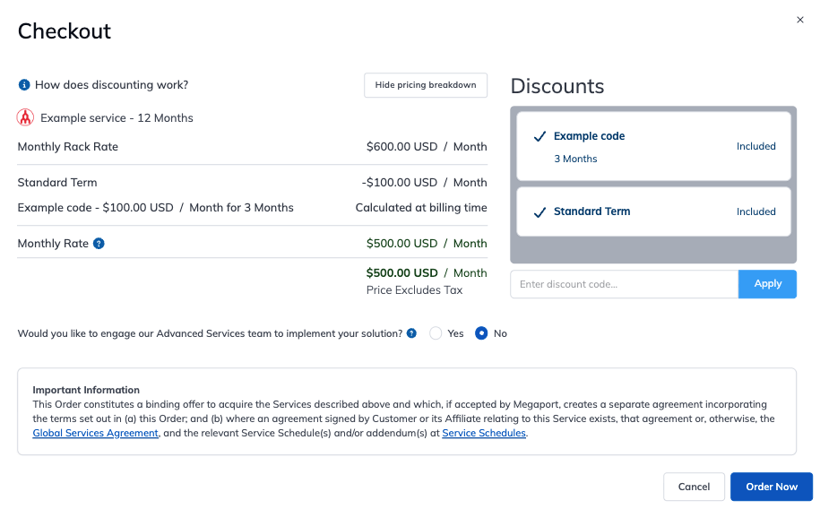
If you entered an incorrect promotion code, you can remove it by clicking Remove.
-
Click Order Now.
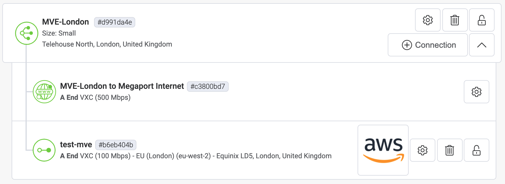
Once the VXC connection is deployed successfully, it appears on the Megaport Portal Services page and is associated with the MVE. Click the VXC title to display the details of this connection. Note that the service status (Layer 2) is up but BGP (Layer 3) will be down because the configuration does not exist yet.
Once deployed in the Megaport Portal, you need to accept the connection in the AWS console and create a Virtual Interface for the connection:
To accept a Hosted Connection
-
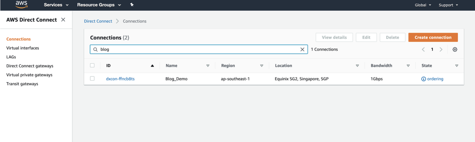
In AWS, go to Services > AWS Direct Connect > Connections and click the connection name.
-
Click Accept at the top right of the window.
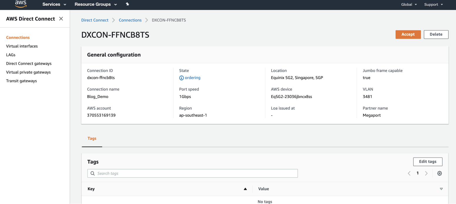
The state will be pending for a few minutes while AWS deploys the connection. After it is deployed, the state changes from ordering to available.
The connection is now available, however you need to create a VIF to connect to AWS services.
Tip
For more information about accepting AWS connections, see the AWS documentation.
Creating a virtual interface
Once you have created and accepted a Hosted Connection, create a VIF and attach the Hosted Connection to a gateway.
Tip
AWS provides detailed instructions for creating Public, Private, and Transit interfaces.
To create and attach a VIF
-
In the AWS console, click Create Virtual Interface.
-
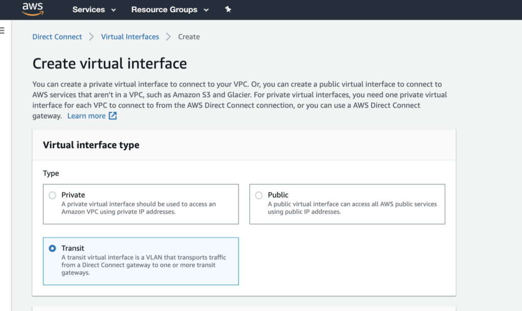
Select the interface type.
The type will vary depending on the type of service you need to access.
- Private – Access resources running into a VPC using their private IP addresses. You can choose to terminate a private virtual interface on a private virtual gateway (to access a single VPC) or to a Direct Connect gateway (and map up to 10 VPCs to the VIF).
- Public – Access all AWS public endpoints, as well as all AWS resources that are reachable by a public IP address.
- Transit – Transport traffic from a Direct Connect gateway to one or more transit gateways.

-
Specify the configuration details:
- Virtual interface name – Enter a name for the virtual interface.
- Connection – The physical connection where you want this virtual interface to be provisioned. The name you provided for the Hosted Connection in the Megaport Portal appears here.
- Virtual interface owner – The account that will own the virtual interface. Select My AWS account.
- Direct Connect gateway – Select the Direct Connect gateway to attach this virtual interface to. A transit VIF is not directly attached to a Transit gateway, but to a Direct Connect gateway.
- VLAN – The VLAN assigned to the virtual interface. Leave this value as is. The VLAN address is populated and appears to be editable; however, you will get an error if you try to change it.
- BGP ASN – Enter the Border Gateway Protocol (BGP) autonomous system number (ASN) for the MVE side of the BGP session.
The following BGP details can be filled out or left blank. When left blank, they are auto-populated by AWS.
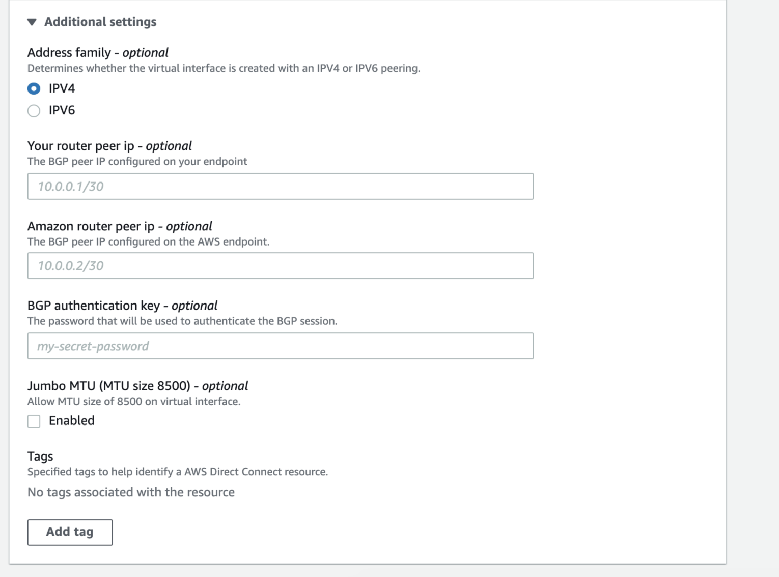
You can also choose whether you want the virtual interface to support Jumbo frames. Enable Jumbo MTU to support an Ethernet packet of 8500 bytes.
-
Click Create virtual interface.
To view the VIF details and state, navigate to Services > AWS Direct Connect > Connections > Name of the Megaport-Created-Hosted Connection.
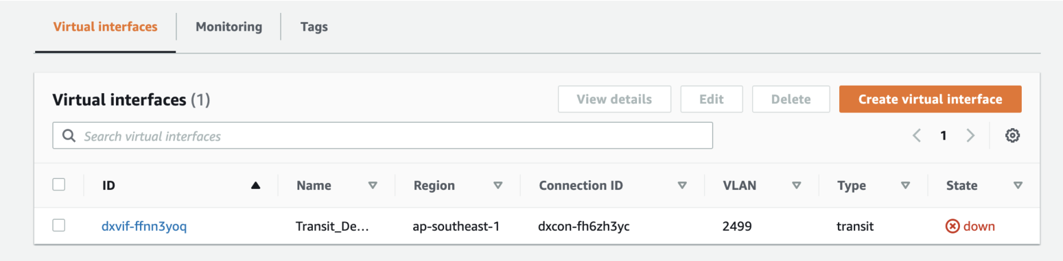
BGP hasn’t been configured, so the interface state appears as down.
Once you accept the connection and create the VIF in AWS, the VXC state changes to configured in the Megaport Portal.
Adding AWS connection details to Versa Director
After you create the connection from your MVE to AWS and set up the connection in the AWS console, you need to configure it in Versa Director. This involves revising Versa Director templates to add a subinterface for the device and configure BGP settings, ASNs, VLANs, and MD5 values.
To add a subinterface in Versa Director
-
Collect the connection details from the AWS console.
Display the details of the Virtual Interface you created in AWS for this Hosted Connection. Note the values for the BGP ASN, BGP Auth Key, Your Peer IP, and Amazon Peer IP.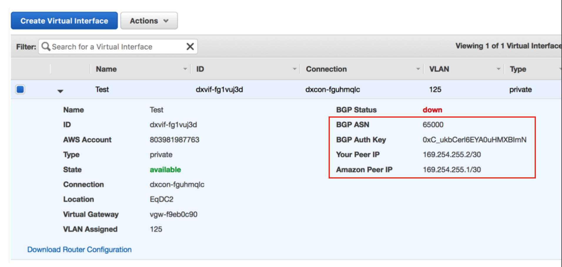
-
Collect the connection details from the Megaport Portal.
To display the details, click the gear icon
 for the AWS connection from your MVE and click the Details view. Note the values for the A-End VLAN.
 -
Log in to Versa Director.
-
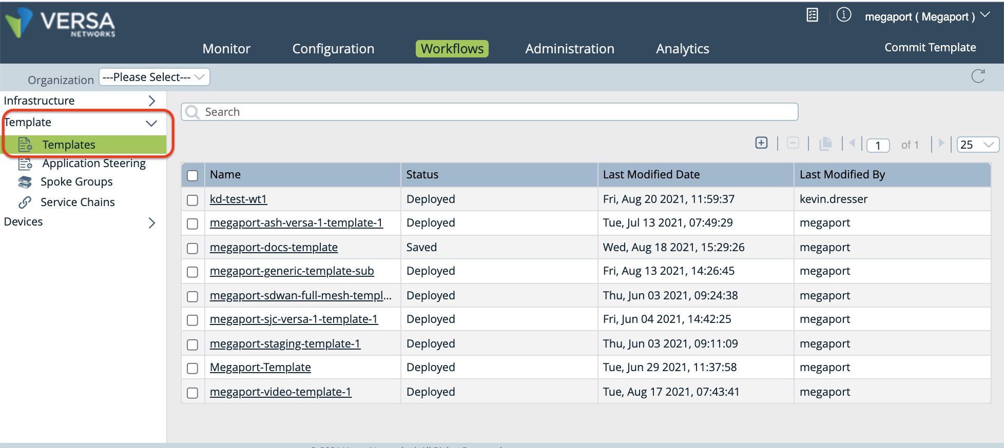
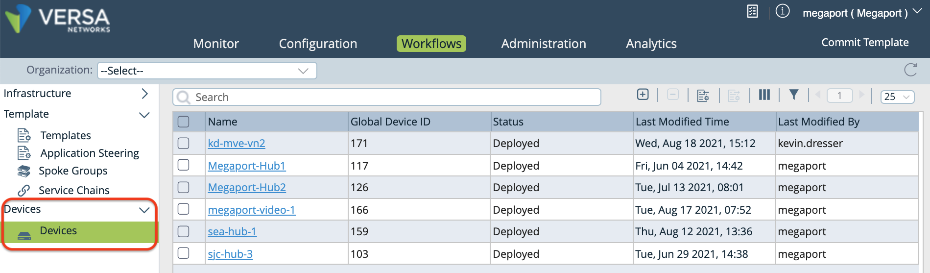
Select the Workflows tab in the top menu bar.
-
Select Template > Templates in the left navigation.
-
Click the template you want to edit, then select the Interfaces tab.
-
In the WAN Interfaces section, locate the Sub Interface column and click
 (Add) to add a subinterface.
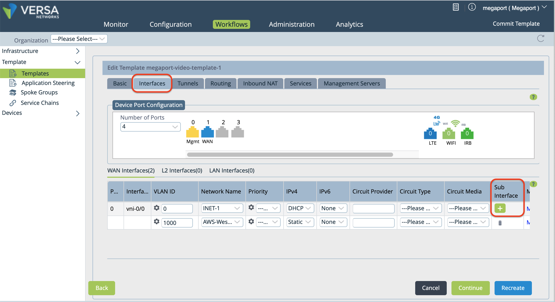
A new row appears in the table.
-
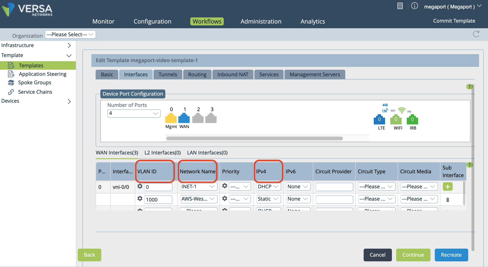
Specify these values for the new subinterface.
-
VLAN ID – Enter the A-End VLAN value from the Megaport Portal (collected in step 2).
-
Network Name – Choose + Create WAN Network from the drop-down menu to open the Create WAN Network window. Specify a meaningful name for the network, click OK, and then select the WAN network you created.
-
IPv4 – Choose Static from the drop-down menu.
-
-
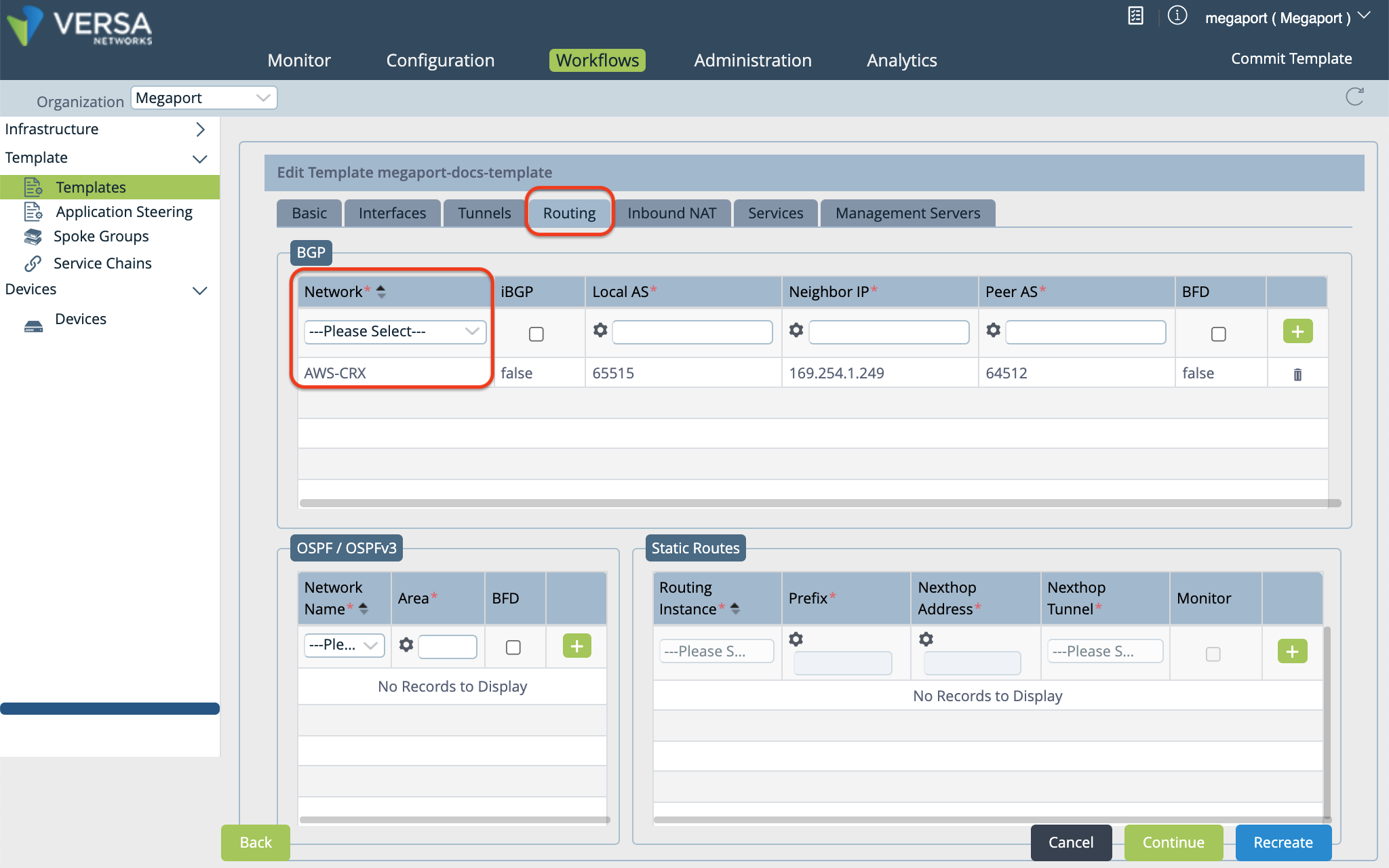
Select the Routing tab to add BGP configuration information.
-
In the BGP section, select the network name in the Network column.
-
Specify the following values according to your MVE configuration:
- Local AS – This is the BGP ASN (your local MVE), collected in Step 1.
- Neighbor IP Address – This is the Amazon Peer IP address, collected in Step 1.
- Peer AS – This is the AWS ASN. By default, this value is 64512.
- Optionally, you can enable BFD (as appropriate for your network).
-
Click
(Add) to the right of the settings. -
Select the Management Servers tab, then click Recreate or Create (at the bottom of the page).
A window opens that shows the differences of the configuration. The auto-merged version is recommended, and selected by default.
-
Click Deploy.
You can use variables in the template to specify values per device for these fields: Router ID, Local AS, Peer AS, Static IP address, and Password.
Note
The Instance ID cannot be modified (the system automatically specifies a value) and Static Address is parameterized by default.
To parameterize Router ID, BGP Local AS, Peer AS, and Password
-
Select the Configuration tab in the top menu bar.
-
Select Templates > Device Templates in the horizontal menu bar.
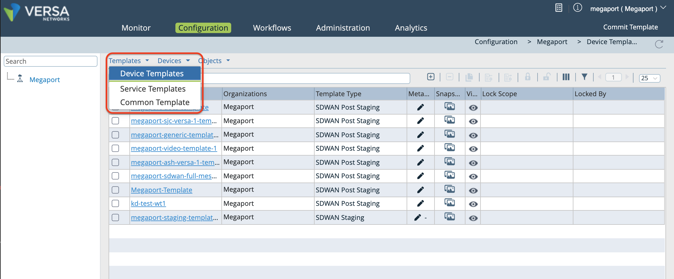
-
Click your template.
By default, the Interfaces column appears.
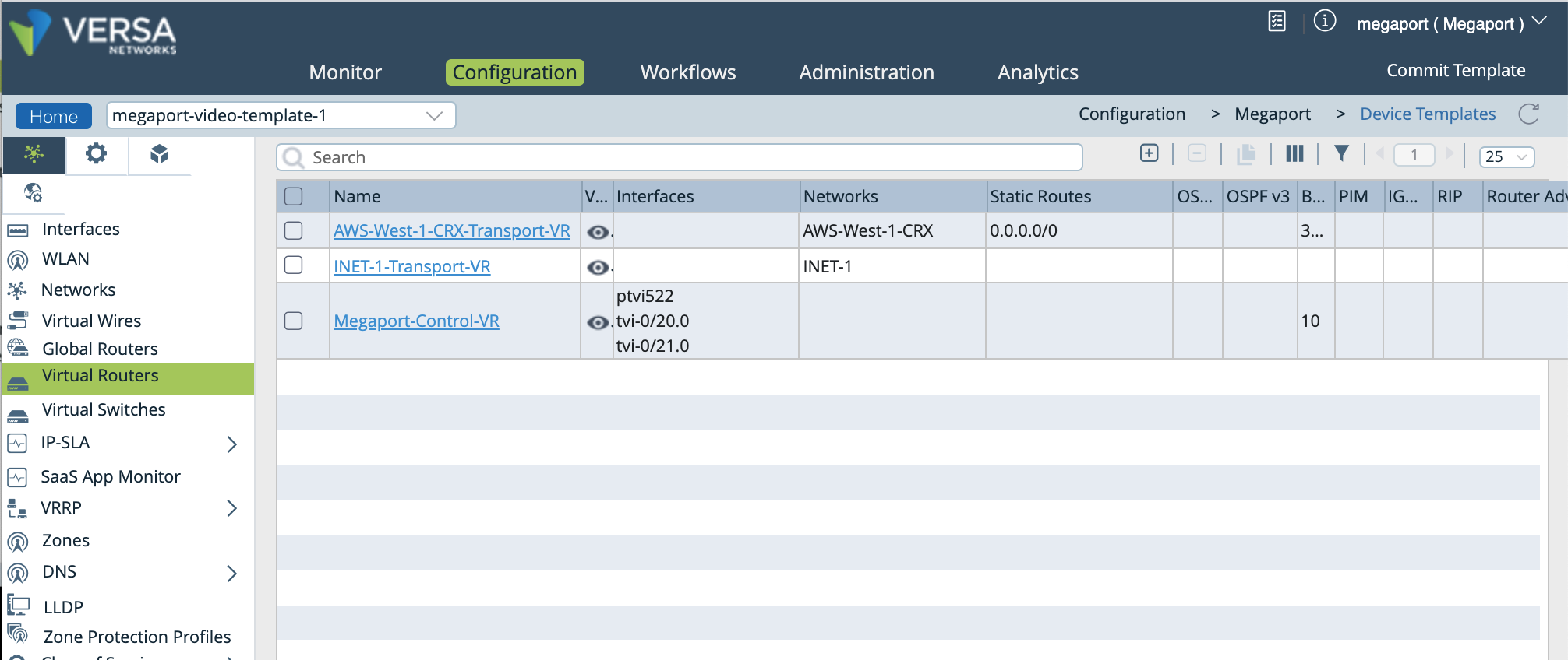
-
In the left navigation, select Virtual Routers, and click your device to open the Edit window.
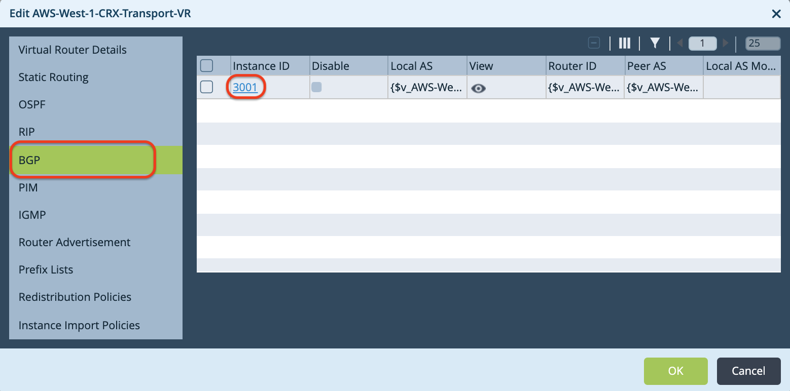
-
In the Edit window, select BGP, then click the Instance ID to open the Edit BGP Instance window.
-
In the Edit BGP Instance window, click
 (Parameterize) next to each of the following fields: Router ID, Local AS, Peer AS, and Password.
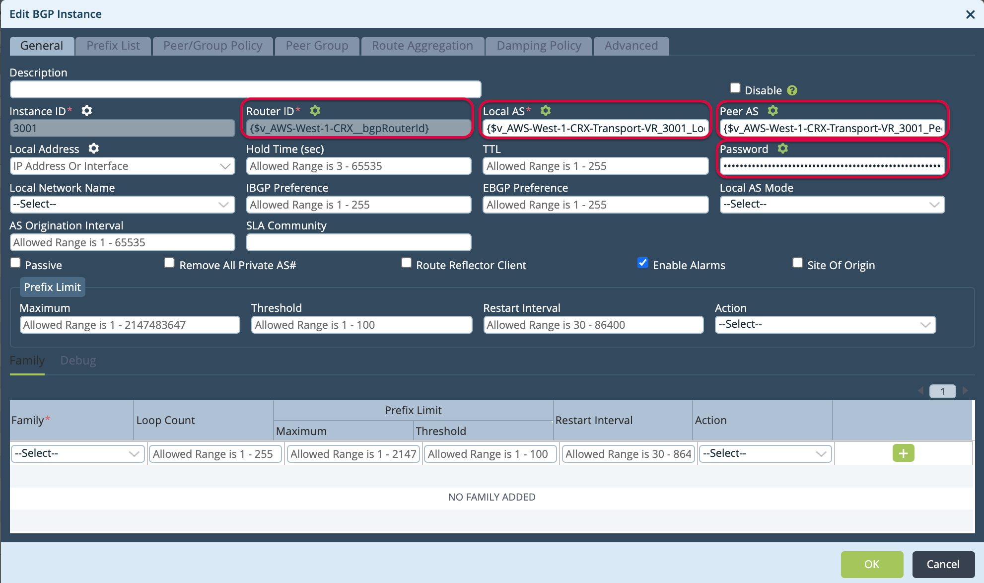
-
Click OK two times to update.
-
Select the Workflows tab in the top menu bar, then select Devices > Devices in the left navigation.
-
Click your device to specify values for the variables you just created.
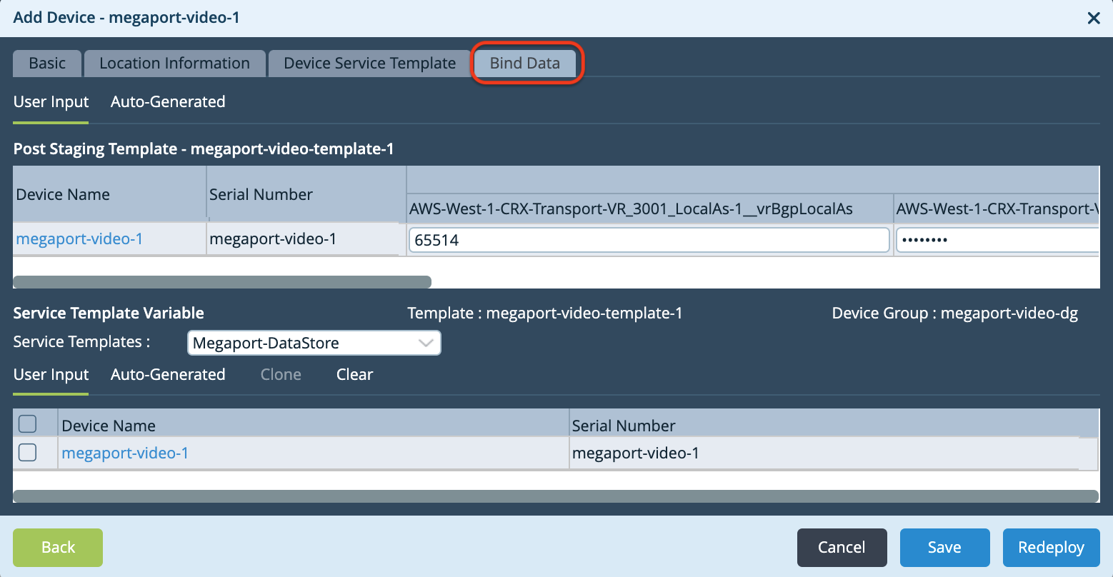
The Add Device window opens.
-
Select the Bind Data tab.
-
Specify values for the variables.
- Local AS – Enter the Customer (MVE) ASN.
- Password – Enter the MD5 password.
- Peer AS – Enter the Amazon-side ASN.
- Router ID – Enter the Customer (MVE) IP address (your local IP address).
- Hop Address – Enter the Amazon IP address.
- Static Address – Enter the Customer IP address (your MVE IP address, including the mask value).
-
Click Redeploy when finished.
When the new configurations for the device are prepared successfully, a green checkmark appears at the bottom of the Versa Director window.
-
To push the changes to the device, click Commit Template (on the upper right).
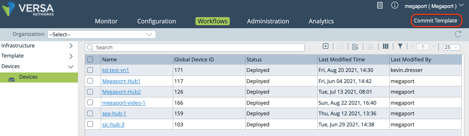
The Commit Template to Devices window opens.
-
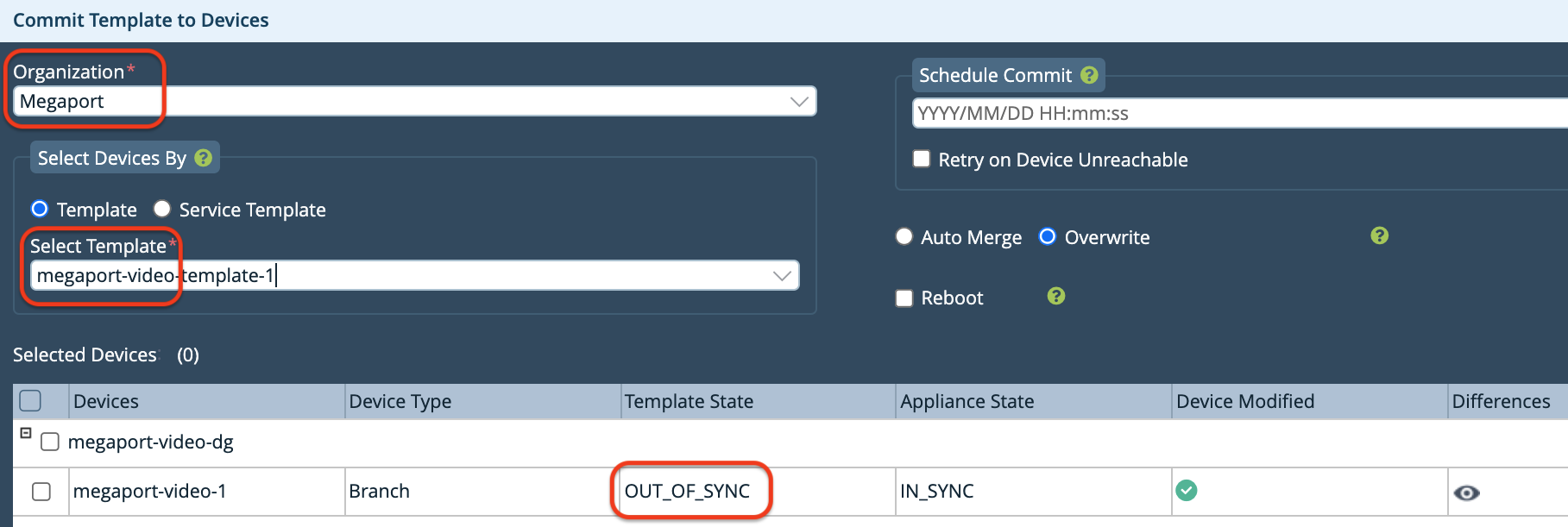
Specify the following in the Commit Template to Devices window:
-
Organization – Select your organization from the drop-down menu.
-
Select Template – Select the template to push to the device from the drop-down menu.
Note that the Template State is OUT_OF_SYNC.
-
-
Click the eye icon in the Differences column to verify your configuration changes.
-
Click Commit to Device.
A green checkmark appears at the bottom right of the screen when the push is successful. The Template State is now IN_SYNC.
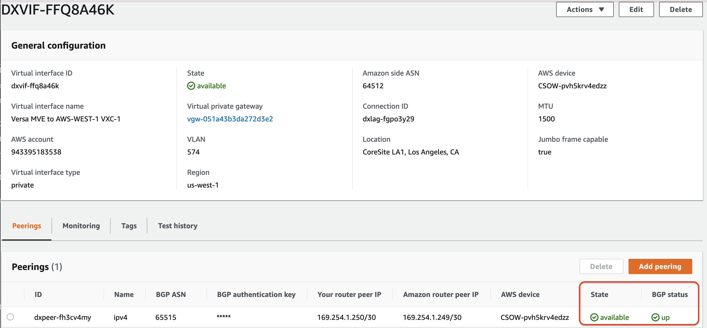
Validating your AWS connection
-
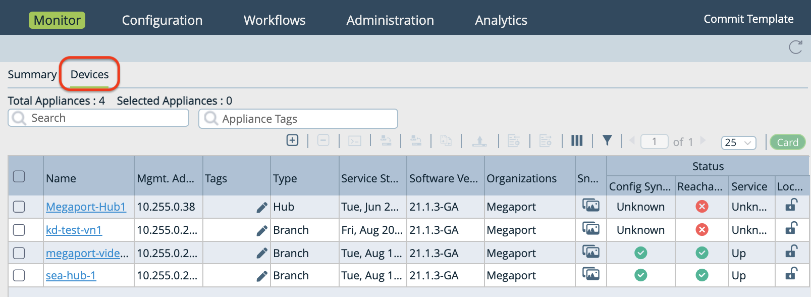
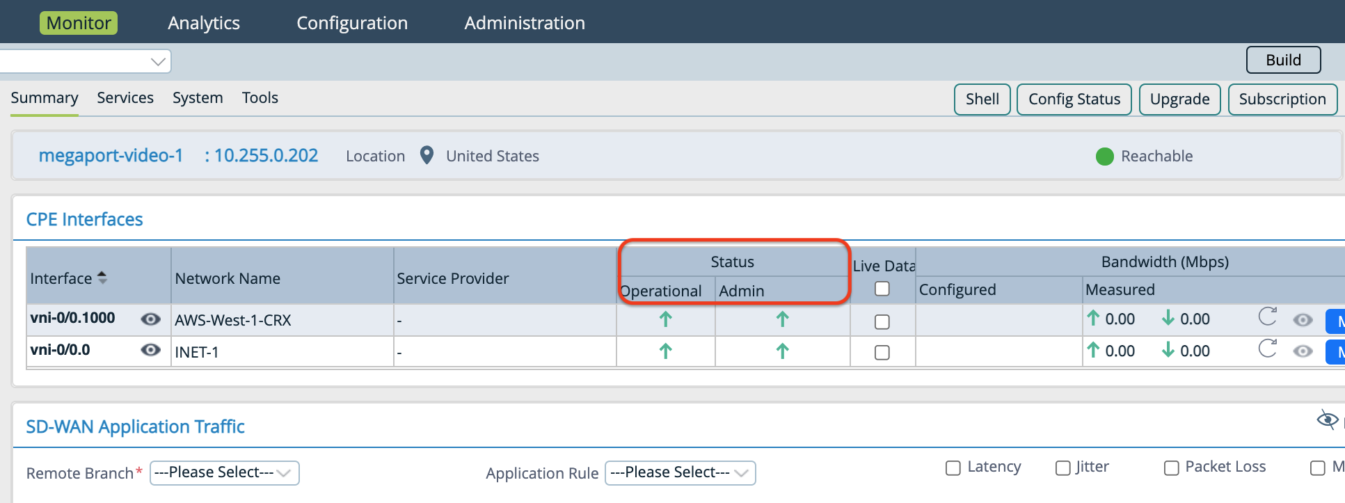
Select the Monitor tab in the top navigation bar, select Devices in the horizontal navigation bar, and then select your device to view details in the Summary screen.
-
In the Summary screen you can review your subinterface in the Interface column, and the Operational and Admin Status.
-
In the AWS Direct Connect portal, refresh the screen and verify that the Virtual interface state is available and BGP Status is up. An AWS BGP session that is up looks like this: