Configuring an MCR
This topic describes how to edit and configure a Megaport Cloud Router (MCR) and Virtual Cross Connect (VXC). Before you begin, you need to create an MCR and configure a VXC, as described in Creating an MCR and Creating an MCR VXC.
Editing an MCR
For each MCR, you can edit any field on the MCR Configuration page, except the rate limit, which is fixed for the duration of the service. The Megaport Marketplace service availability must also be set in your Megaport Marketplace profile. For more information about how to make your service visible to the Megaport Marketplace, see Adding services to your profile.
Note
You can edit the MCR ASN after deployment, but only when there are no VXCs attached. You will need to move or remove all VXCs before editing the ASN. For more information, see Moving VXCs.
To edit an MCR
- Log in to the Megaport Portal and choose Services.
-
Select the MCR you want to edit.
-
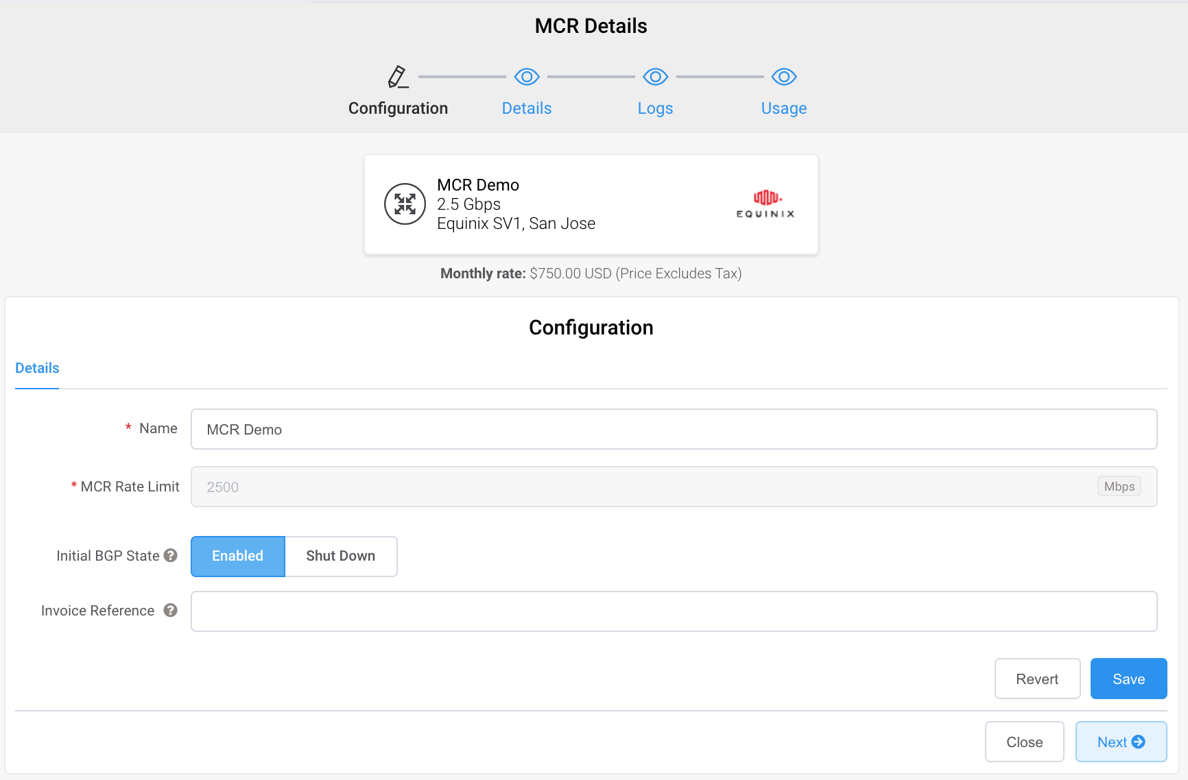
Edit any field on the MCR Configuration page as required, except for the MCR Rate Limit, Megaport Marketplace visibility, and MCR ASN (depending whether a VXC is attached).
-
The Initial BGP State lets you select whether newly created BGP connections are enabled or shut down by default. Select Enabled (the default) if you want any new BGP sessions you configure to be live as soon as you save the configuration. Select Shut Down if you want any new BGP sessions you configure to be left in a shut down state when you save the configuration.
For example, you might want to select the Shut Down option if you are planning to add several BGP sessions across your Virtual Cross Connects (VXCs) but know that you want to do some other router setup before you want them exchanging route information. When you are finished configuring your routers, you can then go into the relevant BGP sessions and enable them.
-
The setting you choose here just sets the default state for the new BGP session. You can override this in the MCR Connection detail screen. For more information about overriding the BGP state for an individual connection, see Shutting down a BGP connection.
For more information, see Creating an MCR.
-
-
Click Save.
Editing a VXC
For each VXC connected to an MCR you can configure one or more interfaces, IP addresses, BGP connections, or static routes. You can also select a NAT source IPv4 address and specify the IP MTU value.
Depending on the VXC destination or CSP provider, the MCR connection settings might have been auto-configured during VXC creation. Follow the steps in this task to configure the connection settings as required.
Note
If the VXC provisioning status is LIVE, CONFIGURED, or DEPLOYABLE, the connection configuration fields will be available when editing a VXC regardless of provider.
To edit a VXC interface
-
Select the MCR VXC you want to edit.
-
Select the VXC A-End or B-End.
-
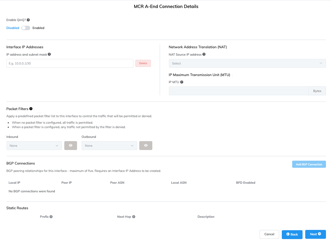
Enter a description for the connection.
-
Enter one or more interface IP addresses and subnet masks to configure on the A-End interface.
-
(Optional) Select a NAT source IPv4 address from the Network Address Translation (NAT) drop-down list.
All packets leaving this interface will have their source NAT rewritten to this address.Network Address Translation (NAT)Network Address Translation (NAT) translates private, unregistered IP addresses used within an organization’s internal network into a single registered public IP address before sending packets to an external network. NAT enables private IP networks to access the internet and cloud services.
allows flexibility in designing a scalable and secure multi-vendor, multicloud, or hybrid cloud scenario. Source NAT translates the source IP address of a packet leaving the MCR. When you assign a NAT IP address in MCR, all packets leaving the interface use that IP address as their source IP address. Enable this feature when NAT is required for a connection, for example, when you need to translate several private IP addresses into a single public IP address to meet Cloud Service Provider (CSP) requirements.For more information about how MCR performs NAT to support public peering types to cloud service providers, see How MCR performs NAT.
-
(Optional) Enter an IP MTU (Maximum Transmission Unit)IP MTU (Maximum Transmission Unit) refers to the largest size (in bytes) of an IP packet that can be sent over a network interface (VXC). Jumbo packets are larger than the standard 1500 bytes (MTU), and are typically used in high-performance networks to reduce overhead and improve efficiency.
value (in bytes) for the VXC.
The IP MTU can range from 1280 to 9070 (9074 if Q-in-Q is disabled). The default value is 1500.
For more information, see MCR Advanced VLAN and Routing Features and Using IPsec with MCR. -
(Optional) If IPsec has been enabled on your MCR, you can configure IPsec tunnels.
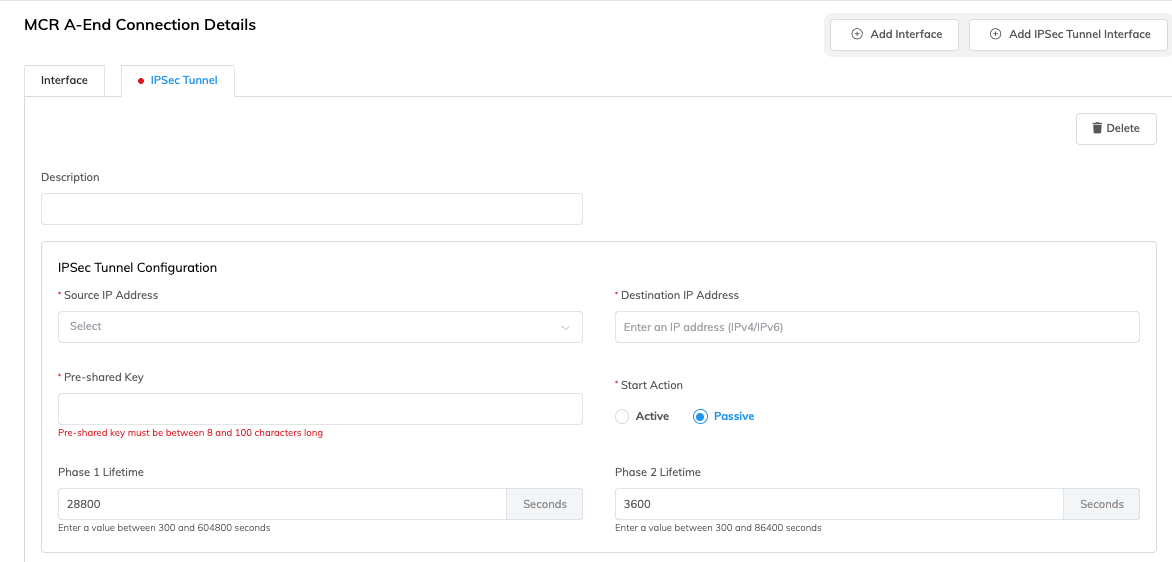
Click + Add IPsec Tunnel Interface.
Add the IPsec tunnel details:- Description – Enter a description of the IPsec tunnel for your reference.
- Source IP Address – Click the box and select the address from the drop-down list.
This is a list of interface IP addresses defined on this VXC. - Destination IP Address – Add the destination IP address.
The destination IP address of the tunnel must not be an IP address configured on the same MCR. - Pre-shared key – Add a key that is common to both the IKE2 (Internet Key Exchange version 2) initiator and responder. The length must be between 8 and 100 characters.
- Local Identifier (optional) – Enter the identifier used for IKE authentication. This allows you to override the default source IP address with a non-IP address, which is required for some configurations. By default, the source IP address is used. Valid values include IPv4/IPv6 addresses, domain names, and email addresses (lowercase, 5-100 characters). For example,
megaport.comoruser@example.com. - Remote Identifier (optional) – Enter the identifier used for IKE authentication. This allows you to override the default destination IP address with a non-IP address, which is required for some configurations. By default, the destination IP address is used. Valid values include IPv4/IPv6 addresses, domain names, and email addresses (lowercase, 5-100 characters). For example,
megaport.comoruser@example.com. - Start Action – Select either active or passive. Passive indicates that the local MCR is an IPsec responder waiting for the remote to perform IKE2 initiation.
- Phase 1 Lifetime – Enter a value between 300 and 604800 seconds. This is the lifetime of IKE2 session in seconds. The default value is 28800 seconds (8 hours). When it expires, rekeying will occur.
- Phase 2 Lifetime – Enter a value between 300 and 86400 seconds. This is the lifetime in seconds of the IPsec Security Association (SA). The value must be less than the Phase 1 Lifetime. The default value is 3600 seconds (1 hour). When it expires, rekeying will occur.
-
Enter any details specific to the VXC type.
- For more information about configuring IPsec, see Using IPsec with MCR.
- For more information about using packet filters, see Using Packet Filters.
- For more information about adding a BGP connection, see Configuring BGP.
- For more information about enabling Bidirectional Forwarding Detection (BFD) settings, see Enabling the BFD protocol.
- For more information about adding a static route, see Configuring static routes.
- For more information about configuring a DHCP server, see Configuring a DHCP pool.
-
Click Save.
Using packet filter lists
Packet filters are used to manage the traffic that is allowed to flow through your MCR. You can apply packet filter lists to your VXC if they have been defined on the MCR. Using packet filter lists is optional.
For more information, see Using Packet Filters.
To apply packet filter lists
-
In the Megaport Portal, go to the Services page.
-
Select the VXC and select the A-End or B-End.
-
Select the packet filter lists to apply from the drop-down lists.
You can select inbound and outbound filters. -
Click Save.
Configuring BGP
The Border Gateway Protocol (BGP)Border Gateway Protocol (BGP) is a standardized routing protocol designed to exchange route and reachability information among autonomous systems (AS) on the internet.
allows dynamic route table updates from the MCR across the VXC to the port. Enable one or more BGP peers for the MCR, up to a maximum of five.
To configure BGP
-
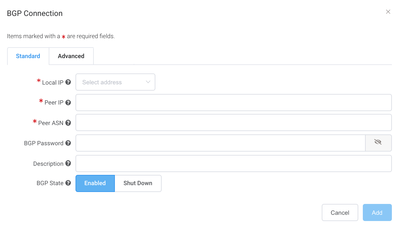
On the MCR Connection detail page, click Add BGP Connection.
-
Specify these values:
-
Local IP – Select the IP address on this interface that communicates with the BGP peer. The drop-down menu is auto-populated based on the address you specified in the connection detail.
-
Peer IP – Specify the IP address for the BGP peer. For example, if the local IP is 198.162.100.1, the peer IP address would be 198.162.100.2.
-
Peer ASN – The ASN of the target routing device that will terminate the BGP connection. The ASN range is from 2 to 4294967294. 4-byte ASNs are supported in the asplain format.
-
BGP Password – The shared key to authenticate the BGP peer. A shared key is optional when creating the VXC, but is required to set up the BGP peering. You can add it after you create the VXC. The shared key length is from 1 to 25 characters. The key can include any of these characters:
a-z
A-Z
0-9
! @ # . $ % ^ & * + = - _Tip
Click the eye icon to see the password as you type. The view persists until you click the eye icon again to hide the password.
-
Description (optional) – Enter a description that will help identify this connection. The description length can range between 1 and 100 characters.
-
BGP State – Shuts down the connection without removing it. The initial setting will be taken from the setting on the A-End of the MCR. Enabling or shutting down the BGP state does not affect existing BGP sessions. The BGP state only affects new VXCs. This setting overrides the MCR state for an individual connection. For more information, see Shutting down a BGP connection and Creating an MCR.
Note
- If you have entered multiple CIDR ranges, the IP addresses are available for selection.
- Use a CIDR calculator to ensure that all data is valid and within range.
-
-
Click Add.
-
Click Next.
To edit a BGP connection
- Select the VXC and select MCR A-End or MCR B-End.
- Next to the BGP connection, click Edit.
- Make your changes.
- Click Update.
For information on the BGP Advanced tab settings, see Configuring BGP Advanced Settings.
Configuring static routes
Static routes establish reachability to peers in place of BGP connections that provide dynamic routing. You configure static routes to provide connectivity to a customer device that doesn’t support BGP or to a target device that requires manually configured addressing and routes. With static routes, you need to manually update any topology changes.
An MCR supports up to 100 static routes.
To add a static route
- Select the VXC and select MCR A-End.
- In the MCR Connection detail page, under Static Routes, specify the IPv4 or IPv6 destination network address in CIDR notation.
- Specify the IPv4 or IPv6 address of the next-hop router.
The address must be in the same subnet as the interface but it cannot match the interface IP address. - (Optional) In the Description field, include any notes that will help identify this static route.
The description range is from 1 to 100 characters. - Click Next.
- Update the MCR B-End, if necessary.
- Click Next.
- Click Update.
To view static routes, see Viewing Traffic Routing through the MCR Looking Glass.
Configuring a DHCP pool
You can configure a DHCPDynamic Host Configuration Protocol (DHCP) is a client/server protocol that automatically provides an Internet Protocol (IP) host with its IP address and other related configuration information such as the subnet mask and default gateway.
pool on an MCR VXC interface to assign IPv4 addresses to devices connected through that interface.
When configured, the MCR acts as a DHCP serverA DHCP (Dynamic Host Configuration Protocol) server automatically assigns IP addresses and essential network configurations like subnet masks, default gateways, and DNS servers to devices.
for the connected network.
Note
DHCP pools are not available on IPsec tunnel interfaces, connections to Megaport Internet, or connections to an Internet Exchange.
To add a DHCP pool
- Select the gear icon on the VXC, then select MCR A-End.
- Under DHCP Pool, click + Add Pool.
-
Specify these values:
- Network – The IPv4 network in Classless Inter-Domain Routing (CIDRClassless Inter-domain Routing (CIDR) notation is a compact representation of an IP address and its associated network mask (subnet mask). For example, the */32 in 192.0.0.1/32 indicates that there is only one address in the range, equivalent to a subnet mask of 255.255.255.255.
For more information, see RFC 4632.
) notation for the DHCP pool. The network must be a valid IPv4 address and must be a subnet of the interface’s IPv4 prefix. The minimum prefix length is /30. For example,192.168.1.0/30.
For more information, see Classless Inter-domain Routing (CIDR). - Start Address – The first IPv4 address in the range to assign to DHCP clients. The address must be within the specified network.
- End Address – The last IPv4 address in the range to assign to DHCP clients. The address must be within the specified network and greater than or equal to the start address.
- Network – The IPv4 network in Classless Inter-Domain Routing (CIDRClassless Inter-domain Routing (CIDR) notation is a compact representation of an IP address and its associated network mask (subnet mask). For example, the */32 in 192.0.0.1/32 indicates that there is only one address in the range, equivalent to a subnet mask of 255.255.255.255.
-
(Optional) Click Add DNS Server to specify one or more DNS resolver IP addresses provided to DHCP clients. You can add up to 5 DNS servers.
- (Optional) Click Add Default Gateway to specify the default gateway IP address provided to DHCP clients.
-
(Optional) Click Add Description to enter a description for the DHCP pool. The description can be up to 100 characters.
-
Click Save.
To delete a DHCP pool
- Select the gear icon on the VXC, then select MCR A-End.
- Under DHCP Pool, click Delete.
- Click Save.
Verifying the BGP configuration
The MCR Looking Glass provides single-screen visibility into the BGP configuration. For more information, see Viewing Traffic Routing through MCR Looking Glass.
To view the BGP status
- In the Megaport Portal, go to the Services page.
- Select the VXC.
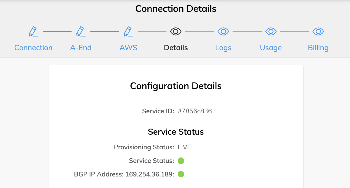
- Choose Details.
The Configuration Details page shows the provisioning, service, and BGP status.
Troubleshooting BGP
If the Services > Connection Detail page displays a status issue, verify these items:
- Select the VXC and select MCR A-End or B-End.
- Under BGP Connections, verify that the correct local ASN is in use for the A-End of the VXC.
- Verify that the correct peer IP address is in use.
- Verify that the correct BGP MD5 password is in use for the A-End of the VXC.
If the BGP configuration looks correct:
-
Make sure that a BGP peer is not blocking ingress or egress from TCP port 179 (BGP) and other relevant ephemeral ports.
-
Verify that a BGP peer is not advertising more than 100 prefixes to AWS. The maximum number of advertised routes to AWS is 100. The BGP session is disabled if it exceeds the prefix limit of 100 advertised routes.
Shutting down a BGP connection
Use this setting to temporarily disable the BGP session without removing it. BGP shutdown provides a way to administratively shut down a BGP connection while setting up a new route, performing maintenance, troubleshooting, and so on.
To temporarily disable a BGP connection
-
In the Megaport Portal, go to the Services page.
-
Select the VXC and select the A-End or B-End.
-
After the BGP connection details, click Shut Down.
-
Click Yes to confirm.
Setting up MCR BGP notifications
You can receive email notifications whenever a Border Gateway Protocol (BGP)Border Gateway Protocol (BGP) is a standardized routing protocol designed to exchange route and reachability information among autonomous systems (AS) on the internet.
session status changes on your MCR. These changes can include BGP going up, down, or flapping. If a session is flapping, only one email per hour will
be sent.
You can opt in or out of receiving these email notifications.
MCR BGP notifications email specifications
The MCR BGP notification system is designed to provide timely notifications for BGP up, down, or flapping events while minimizing alert noise.
The notification system implements rate limiting for rapidly changing status, as described below.
- The initial notification is sent immediately.
- Subsequent events within one hour are suppressed.
- The email body will indicate if the event has repeated during the suppression period.
To receive BGP email notifications
- Visit the Megaport Portal and log in.
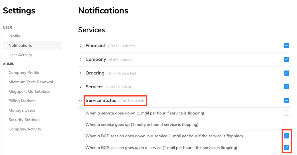
- Choose User Menu > User Settings > Notifications.
- Click the Service Status notification group to view the BGP email notification types.
- Select the notification group check box to subscribe to all notifications in that group, or subscribe to individual notification types. Any notification subscription changes are automatically saved.
Configuring flow export
Flow export enables IP Flow Information Export (IPFIXIPFIX (IP Flow Information Export) is an IETF standard protocol (RFC 7011) that defines a universal method for exporting IP flow information from network devices such as routers, switches, and firewalls to a collector. It is the standardised successor to Cisco’s NetFlow v9, using a template-based model that allows exporters to define the structure of the data they send, making the format flexible and extensible. IPFIX is commonly used for network traffic monitoring, capacity planning, security analysis, and billing purposes.
) on MCR services, allowing you to export network flow records to external collectors for traffic analysis, capacity planning, and security monitoring.
You can configure up to three flow export targets for each MCR. Flow records are exported using either the UDP or TCP transport protocol.
A flow export target specifies the destination to which flow records are sent.
Requirements
Before configuring flow export, ensure that your service meets these requirements:
- The MCR must be in a Live or Configured provisioning state.
- You must have a flow collector ready to receive IPFIX data.
- The MCR must have an active route to the collector via any attached VXC.
Validation rules
These validation rules apply when configuring flow exporters:
- Maximum Targets – Each service supports up to three flow export targets.
- Target IP Address – Cannot be a reserved or loopback address (for example, 127.0.0.1).
- Target Port – Must be between 1 and 65535.
- Address Family – If you specify a Local IP Address, it must be the same address family (IPv4 or IPv6) as the Target IP Address.
- Uniqueness – The combination of Target IP Address, Target Port, and Protocol must be unique within the service.
To configure flow export
-
In the Megaport Portal, go to the Services page.
-
Click the gear icon next to the MCR.
-
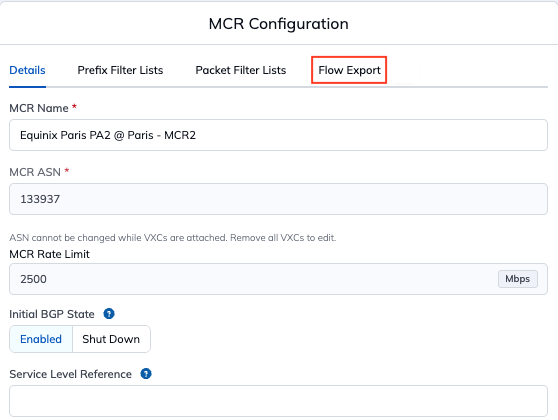
On the MCR Configuration page, select the Flow Export tab.
-
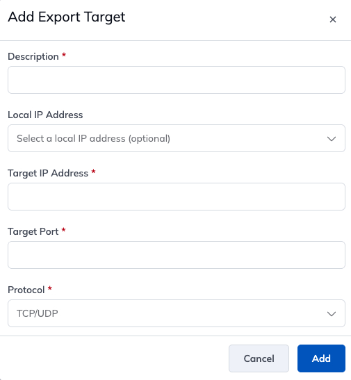
Click Add Export Target.
The Add Export Target page appears.
-
Specify the configuration details:
- Description – Enter a name to identify this flow export target.
- Local IP Address (optional) – The source IP address on the service for the flow export stream. Select an address configured on the service, or leave blank to use the default.
- Target IP Address – Enter the IPv4 or IPv6 address of your flow collector.
- Target Port – The port number of the flow collector (1-65535). Enter the port number your collector listens on.
- Protocol – Select UDP or TCP.
-
Click Add.
The new flow export target configuration details are displayed in the table.
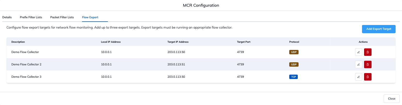
Note
A maximum of three IPFIX export targets can be configured per service. Each target must have a unique combination of the Local IP Address and collector targets (Target IP Address, Target Port and Protocol).
To edit a flow export configuration
-
In the Megaport Portal, go to the Services page.
-
Click the gear icon next to the MCR.
-
On the MCR Configuration page, select the Flow Export tab.
-
In the row for the flow export configuration you want to edit, click Edit.
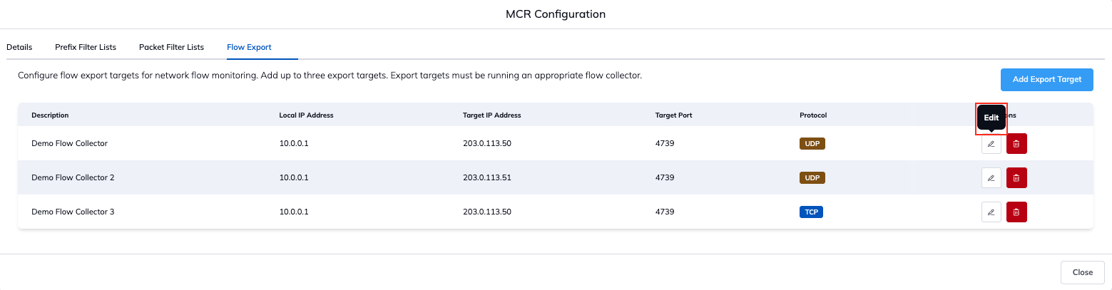
-
Update the configuration details as required.
-
Click Save.
To delete a flow export configuration
Warning
Deleting a flow export target immediately stops exporting flow records to that collector. This action cannot be undone.
-
In the Megaport Portal, go to the Services page.
-
Click the gear icon next to the MCR.
-
On the MCR Configuration page, select the Flow Export tab.
-
In the row for the flow export configuration you want to remove, click Delete.
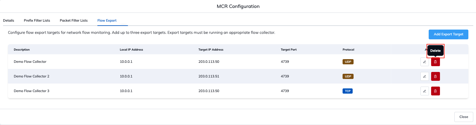
-
In the confirmation prompt, click Delete Target.