Creating MVE Connections to Any Endpoint with Palo Alto VM-Series
This topic describes the general steps to configure and deploy a Megaport VXC connection in the Megaport Portal and integrate it with an MVE in Palo Alto VM-Series. The VXC can connect to a Cloud Service Provider, a Port, or an MCR.
Step 1 – Create an MVE
- Create an MVE in the Megaport Portal.
For more information, see Creating an MVE. The MVE needs to be in the active state.
Step 2 – Create a VXC from the MVE
- In the Megaport Portal, select the MVE created in Step 1.
- Create a VXC to another MVE, a Port, or Cloud Service Provider.
For more information, see Creating a VXC. Ensure both ends of the connection are active and have BGP configured. - In the connection details, note the A-End VLAN.
Step 3 – Collect these values for the connection
- MVE IP address
- MVE VLAN (A-End)
- MVE ASN
- Cloud/B-End IP address
- B-End ASN
- MD5 Password
Step 4 – Create an interface in VM-Series
-
Log in to VM-Series.
-
Choose Network > Interfaces.
-
Click Add Subinterface.
-
Provide these details:
- Interface Name – Specify a meaningful name for the interface.
- Comment – Enter an alternate name.
- Tag – Specify the A-End inner VLAN value for the connection.
- Virtual Router – Select a virtual router to the interface, as required by your network.
- Type – Choose VLAN.
-
Select the IPv4 tab.
- Select Static as the Type.
- Click +Add to add a new IP address.
- Enter the IPv4 address and netmask for the MVE.
- Click OK.
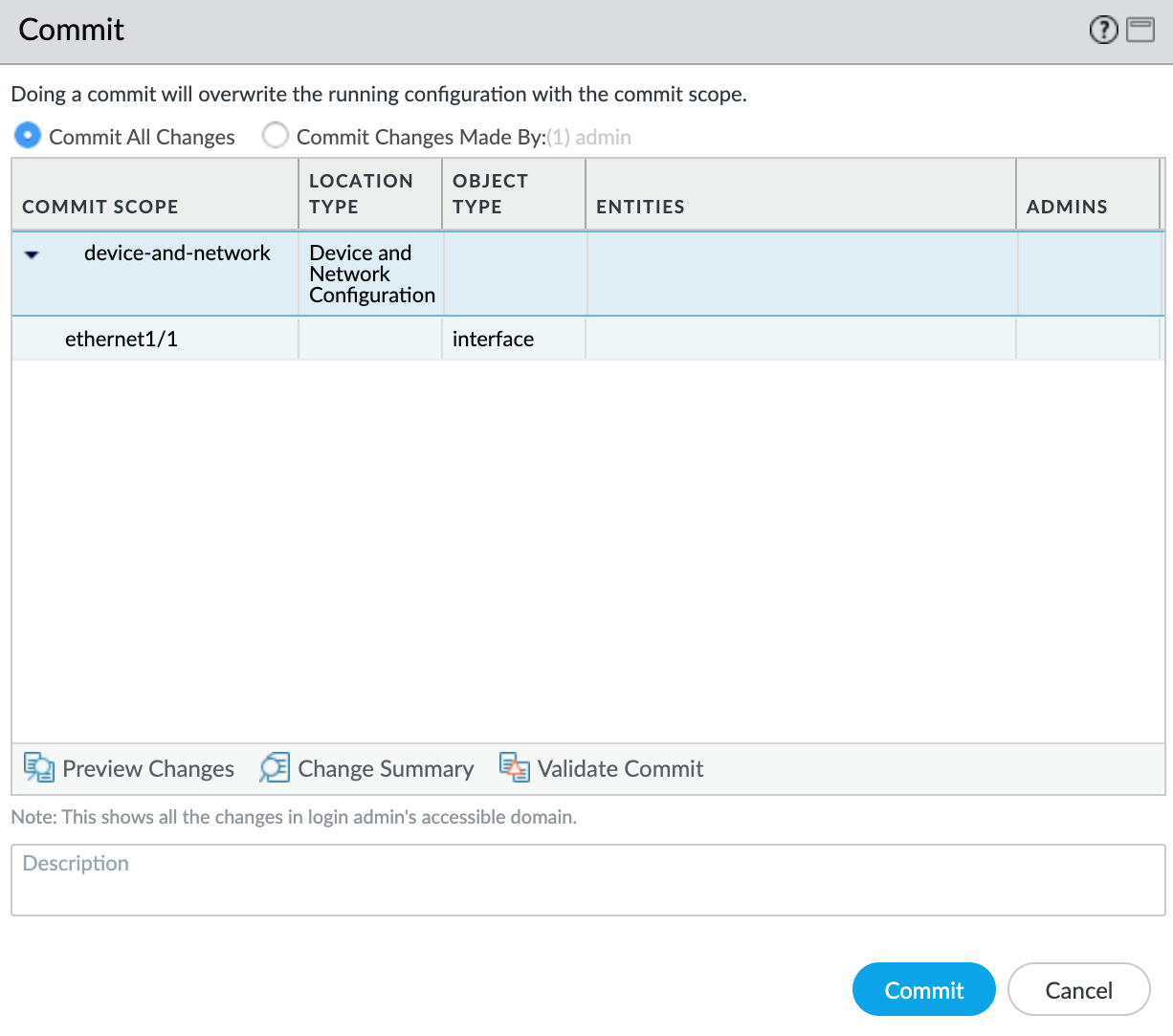
- Click Commit in the top right corner.
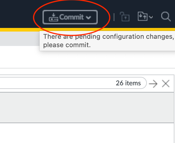
- Review the changes and click Commit.
The new VLAN interface appears with your physical interface.
Next, you will create a security zone so the interface can route traffic.
To create a security zone
- Select the
ethernet1/1.1010subinterface. - Select New Zone from the Security Zone drop-down list.
- Specify a name for the security zone.
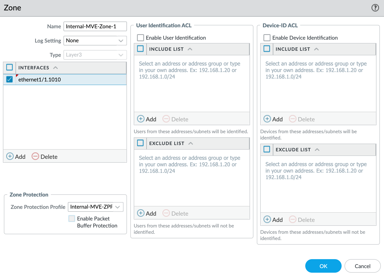
- Click +Add under Interfaces and add
ethernet1/1.1010to the security zone. - Specify any additional details as required for your network security.
- Select New Zone Protection Profile from the Zone Protection Profile drop-down list.
- Specify any details as required for your network security. This example uses all the defaults.

- Click OK.
- Click OK in the Layer3 Subinterface screen.
- Click Commit in the top right corner.
- Review the changes and click Commit.
Step 5 – Configure BGP
To create the BGP session
- In VM-Series, choose Network > Virtual Routers.
- Select the virtual router.
- In the left pane, select BGP.
- Provide the following BGP details:
- Enable – Select this check box to start the BGP session after committing these changes.
- Router ID – Enter the B-End IP address (cloud provider, port, or other MVE).
- AS Number – Provide the ASN for the MVE connection.
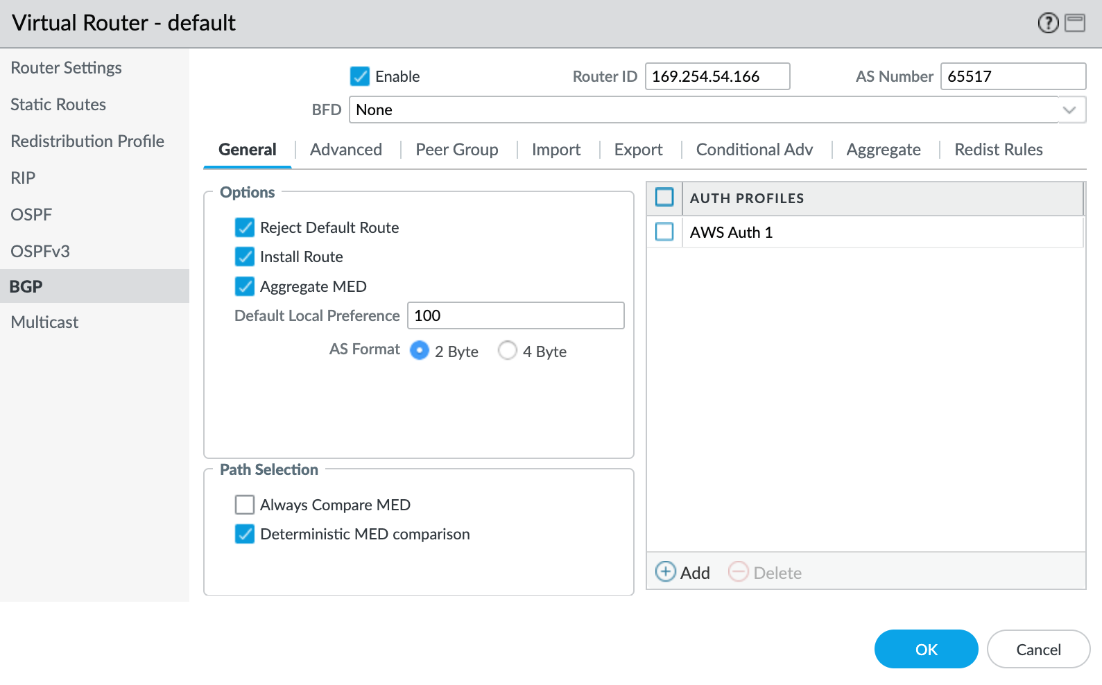
- Click +Add under Auth Profiles.
- Specify a Profile Name.
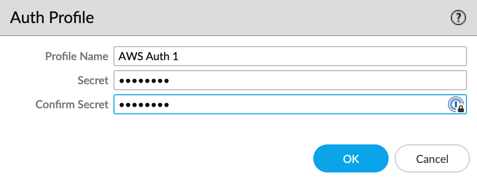
- Enter and confirm the auth password.
- Click OK.
- Select the Peer Group tab.
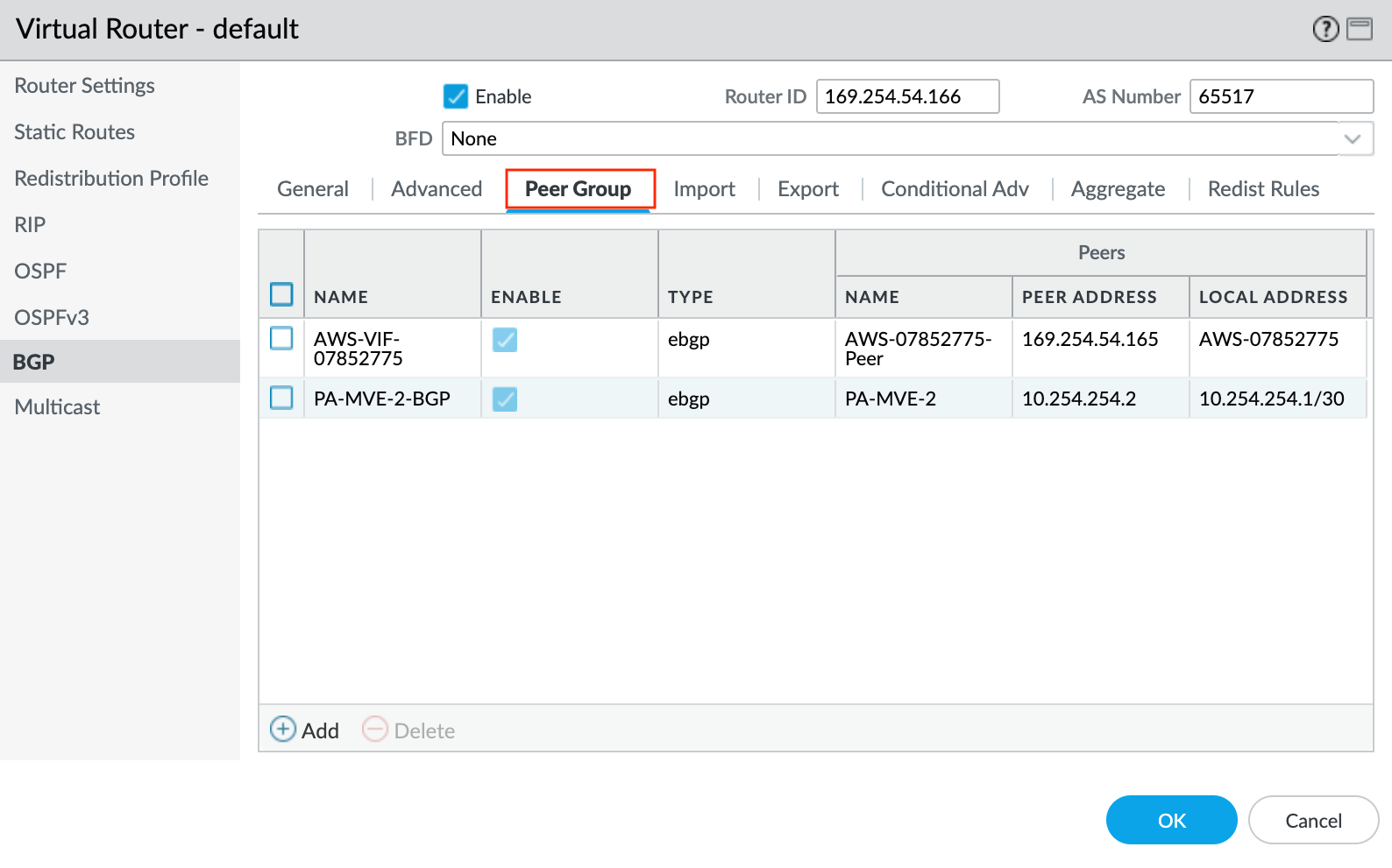
- Click +Add to add a peer group.
- Specify a name for the peer group.
- Specify eBGP as the session type.
- Specify any additional details as required for your network.
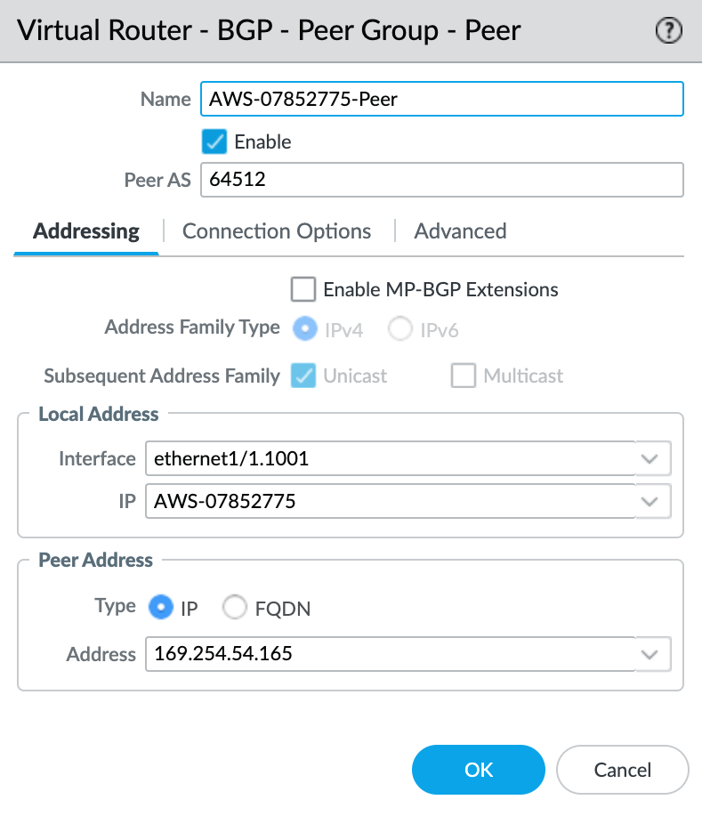
- Click +Add to add a new peer.
- Specify the details for the peer:
- Name – Specify a name for the peer.
- Peer AS – Specify the B-End autonomous system number (ASN).
- Local Address – Select the proper subinterface and IP address from the drop-down list.
- Peer Address – Enter the B-End IPv4 address.
- Select the Connection Options tab.
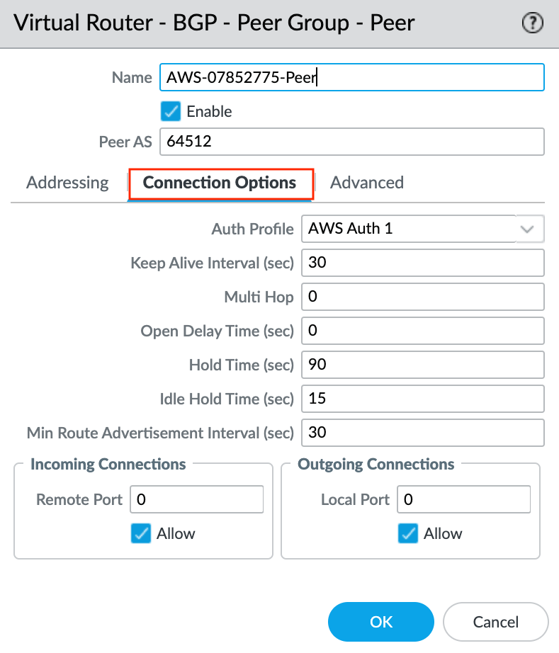
- Select the previously created Auth Profile.
- Click OK in the Peer Group - Peer screen.
- Click OK in the BGP - Peer Group/Peer screen.
- Click OK in the Virtual Router screen.
- Click Commit in the top right corner.
- Review the changes and click Commit.
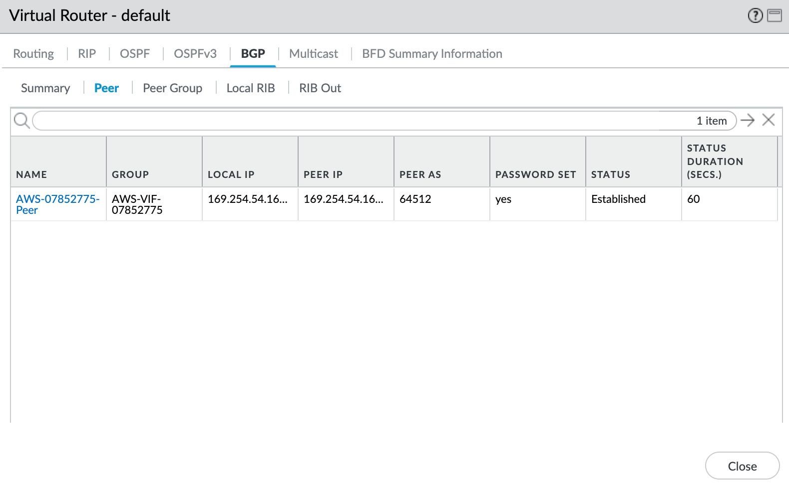
Step 6 – Validating your connection
To check the connection status
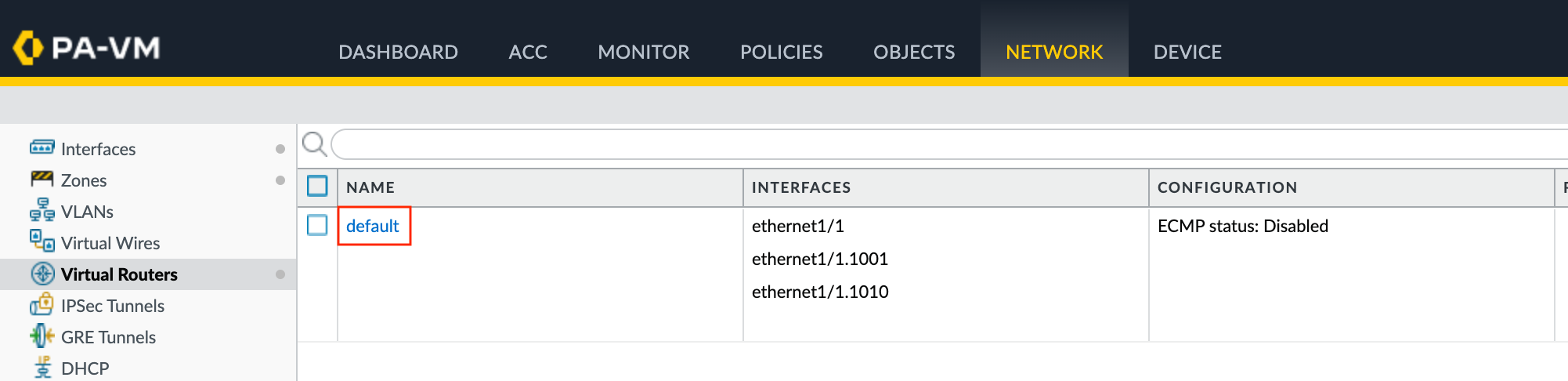
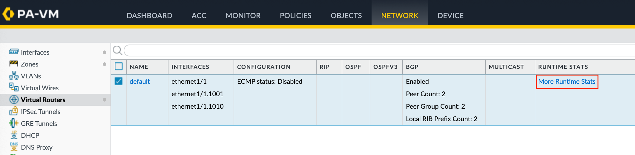
- Choose Network > Virtual Routers.
- Locate your virtual router (default).
- Click More Runtime Stats in the Runtime Stats column on the right.
- Select the BGP tab, and then select the Peer tab.
- Verify that the peer status is Established.