Connecting MVEs Integrated with Palo Alto Networks VM-Series
This topic describes how to connect a Megaport Virtual Edge (MVE) integrated with Palo Alto Networks next-generation firewall (NGFW) to another MVE.
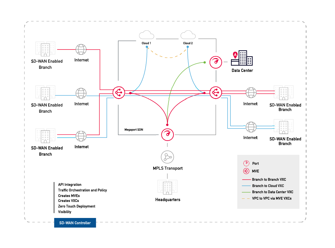
This deployment uses the Megaport private software defined network (SDN) to reduce reliance on the internet and connect enterprise branch locations.
With two MVEs configured, you can create a private VXC to connect them on the Megaport network without the need for any physical infrastructure. A VXC is essentially a private point-to-point Ethernet connection between an A-End MVE and a B-End MVE.
Note
The internet-facing interface on an MVE can reach the internet-facing interface on another MVE over the public internet. That is, you can exchange traffic from MVE to MVE in different metros over the internet, within the same country. The basic connection model consists of an MVE at one metro connecting via a Megaport Internet connection to an MVE at another metro. Connectivity consists of a customer/SD-WAN partner-managed connection, not Megaport managed. For more information, see Megaport Internet Overview.
Before you begin
- Provision two MVEs in different locations. If you haven’t already created MVEs, see Creating a VM-Series MVE.
Creating a VXC between two MVEs
A private VXC deployment between two MVEs integrated with Palo Alto Networks starts in the Megaport Portal. To complete the configuration, you will use Palo Alto Networks VM-Series.
To create a VXC
-
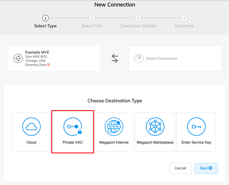
In the Megaport Portal, go to the Services page and click +Connection next to the originating A-End MVE.
-
Select Private VXC.
-
Select the destination B-End MVE and location.
Use the Country filter to narrow the selection. -
Click Next.
-
Specify the connection details:
-
Connection Name – The name of your VXC to be shown in the Megaport Portal. Specify a name for the VXC that is easily identifiable, for example, LA MVE 2 to Dallas MVE 4. You can change the name later, if you like.
-
Service Level Reference (optional) – Specify a unique identifying number for the VXC to be used for billing purposes, such as a cost center number or a unique customer ID. The service level reference number appears for each service under the Product section of the invoice. You can also edit this field for an existing service.
-
Rate Limit – The speed of your connection in Mbps. The maximum speed is displayed. Although the rate limit for a VXC can be up to 10 Gbps, the compute capacity of the A-End or B-End MVE can influence the circuit throughput. Consult Palo Alto Networks’ documentation for more information.
-
VXC State – Select Enabled or Shut Down to define the initial state of the connection. For more information, see Shutting Down a VXC for Failover Testing.
Note
If you select Shut Down, traffic will not flow through this service and it will behave as if it was down on the Megaport network. Billing for this service will remain active and you will still be charged for this connection.
-
vNIC selection – Depending on the definition of the MVEs you are using, you might have to specify A-End and B-End vNICs.
-
A-End vNIC – Specify a vNIC by using the pre-populated default, or select from the drop-down list.
-
B-End vNIC – Specify a vNIC by using the pre-populated default, or select from the drop-down list.
For more information on vNIC selection when connecting MVEs with different services, see Types of vNIC Connections.
-
-
Preferred A-End VLAN – Specify the 802.1q VLAN tag for this connection for the A-End.
Each VXC is delivered as a separate VLAN on the MVE. The VLAN ID must be unique on this MVE and can range from 2 to 4093. If you specify a VLAN ID that is already in use, the system displays the next available VLAN number. The VLAN ID must be unique to proceed with the order. If you don’t specify a value, Megaport will assign one. For a Palo Alto Networks MVE, it will also be used to configure the VLAN tag in Palo Alto Networks PAN-OS. -
Preferred B-End VLAN – Specify the 802.1q VLAN tag for this connection that you will receive through the B-End VLAN. For a Palo Alto Networks MVE, it will also be used to configure the VLAN tag in Palo Alto Networks PAN-OS.
-
Minimum Term – Select No Minimum Term, 12 Months, 24 Months, or 36 Months. Longer terms result in a lower monthly rate. 12 Months is selected by default.
Take note of the information on the screen to avoid early termination fees (ETF). See VXC Pricing and Contract Terms and VXC, Megaport Internet, and IX Billing for more information.
-
-
Click Next to view the Summary page.
-
Confirm the configuration and click Add VXC.
-
Click Order to proceed through the checkout process.
Once the VXC is deployed, you can view it in the Megaport Portal Services page. The Services page displays the VXC under the A-End MVE and the B-End MVE. Note that the service identifier number is the same for the VXC at both ends of the connection.
The next step is to configure the A-End and B-End MVEs in the Palo Alto Networks VM-Series.
Note
The next procedure configures IP connectivity with BGP, providing just one solution out of many. Consult your vendor documentation for specific network design and configuration options before configuring interfaces for the MVEs.
Configuring the A-End MVE in VM-Series
-
Log in to your VM-Series instance.
-
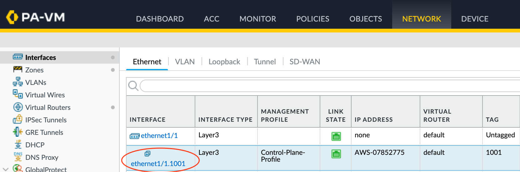
Choose Network > Interfaces.
-
Select the A-End MVE (
ethernet1/1). -
Click Add Subinterface.
-
Provide these details:
-
Interface Name – Enter a name for the subinterface. In the adjacent field, enter a number to identify the subinterface.
-
Comment – Enter an alternate name, for example, PA-MVE-1 to PA-MVE-2.
-
Tag – Specify the VLAN value associated with the VXC you created earlier. For ease of use, specify the same number as the Interface Name.
-
Virtual Router – Select a virtual router to the interface, as required by your network.
-
-
Select the IPv4 tab.
- Select Static as the Type.
- Click +Add to add a new IP address.
- Enter the IPv4 address and netmask.
- Click OK.
- Click Commit in the top right corner.
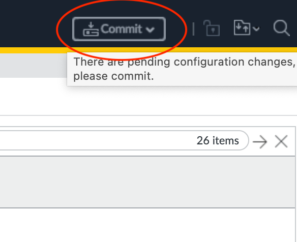
- Review the changes and click Commit.
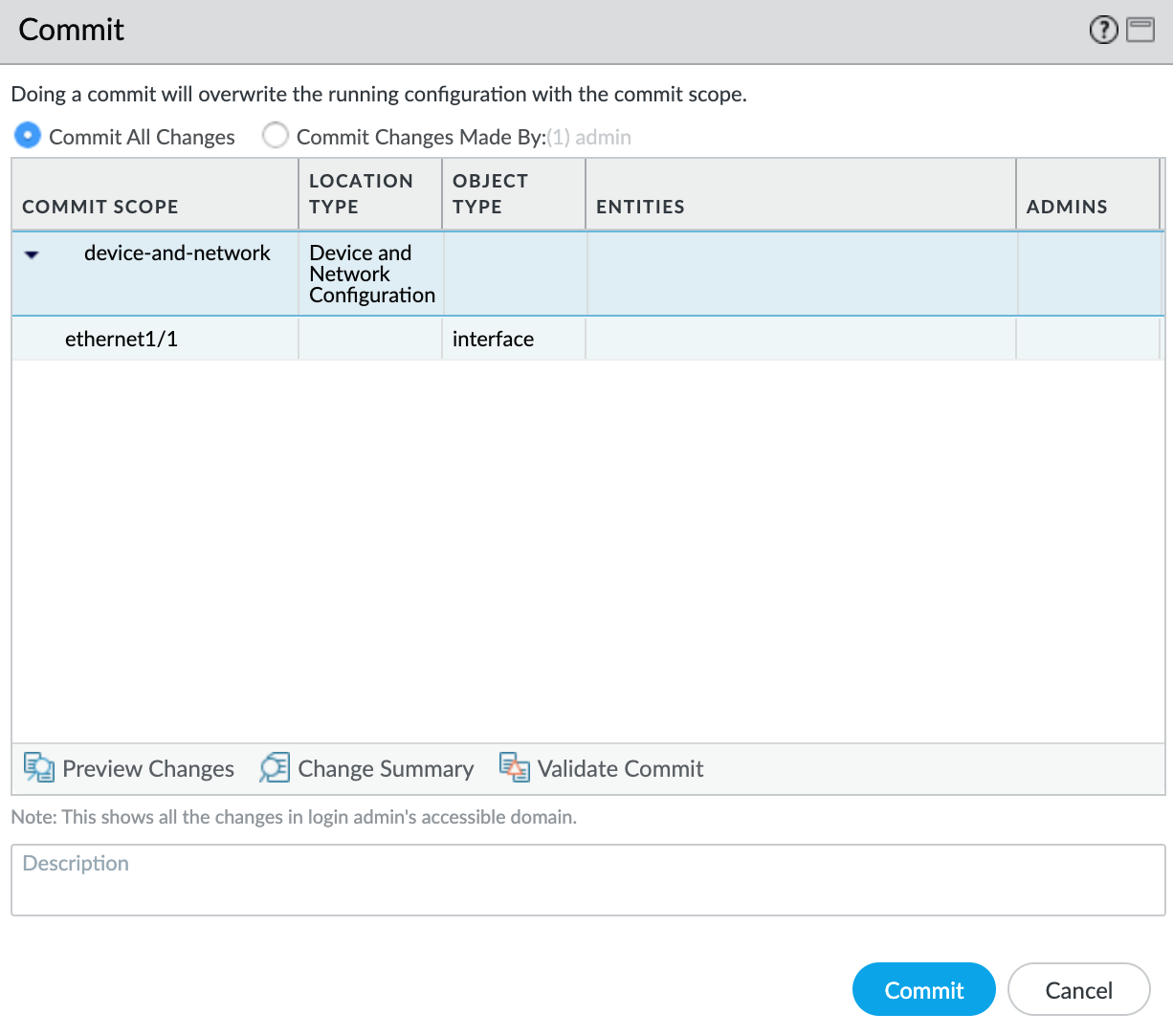
The new VLAN interface appears with your ethernet1/1 physical interface.
Next, you will create a security zone so the interface can route traffic.
To create a security zone
- Select the
ethernet1/1.1010subinterface. - Select New Zone from the Security Zone drop-down list.
- Specify a name for the security zone.
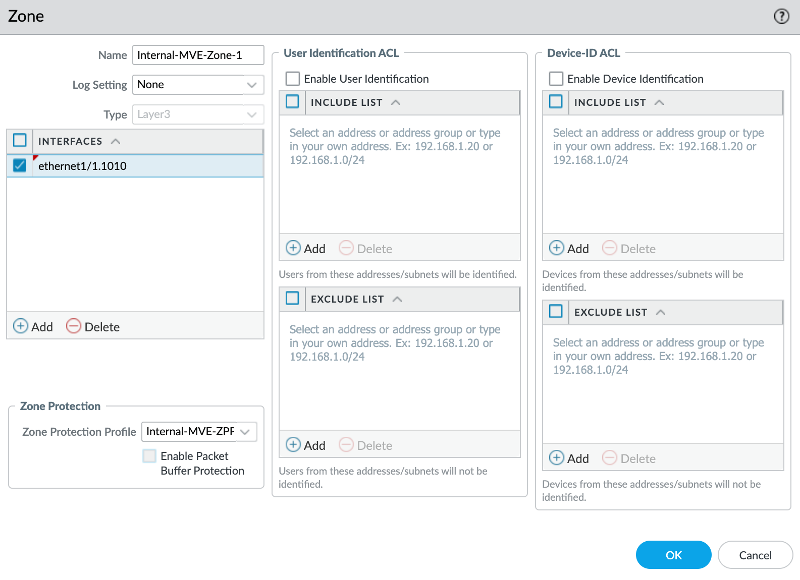
- Click +Add under Interfaces and add
ethernet1/1.1010to the security zone. - Specify any additional details as required for your network security.
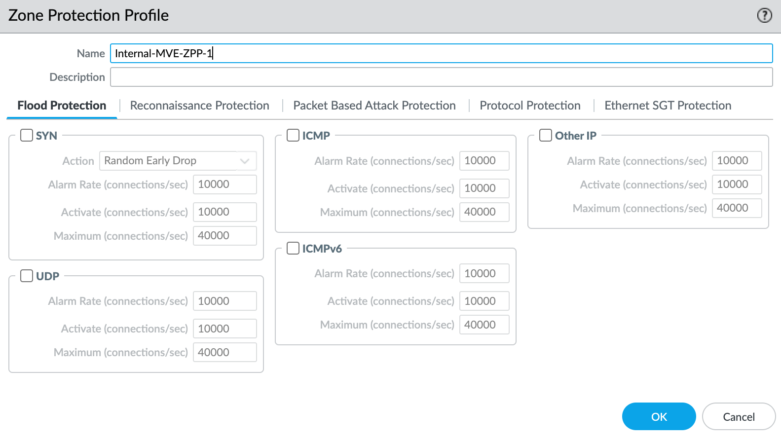
- Select New Zone Protection Profile from the Zone Protection Profile drop-down list.
- Specify any details as required for your network security. This example uses all the defaults.
- Click OK.
- Click OK in the Layer3 Subinterface screen.
- Click Commit in the top right corner.
- Review the changes and click Commit.
Configuring the B-End MVE in VM-Series
- Follow the same procedure to configure the B-End interface, using a different IP address.
Validating your connection
Next, you will test connectivity between the Palo Alto Networks MVEs.
Note
Because Palo Alto is a firewall, you must enable ICMP before an interface can respond to an ICMP echo request.
To validate your connection
- Log in to your VM-Series instance.
- Choose Network > Interfaces.
- Select the newly created subinterface.
- Select the Advanced tab.
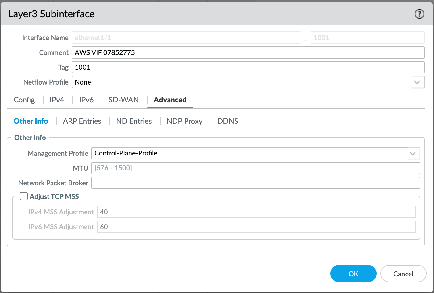
- Select New Management Profile from the drop-down list.
- Specify a profile name in the Name field.
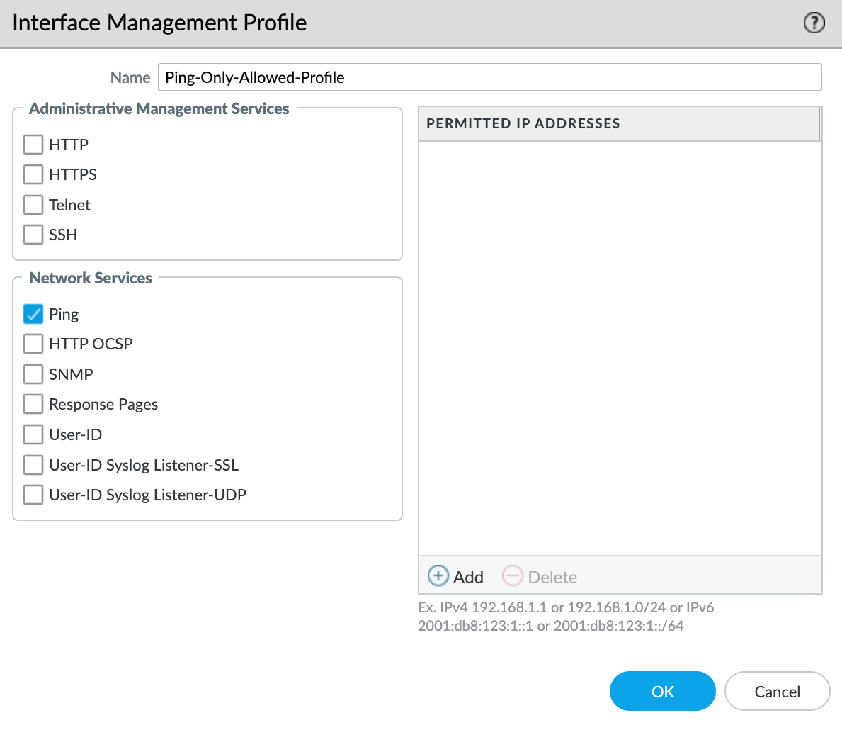
- Select Ping from the Network Services list.
- To add specific IP addresses or subnets to the ACL, click +Add under Permitted IP Addresses.
- Click OK.
- Click OK.
- Click Commit in the top right corner.
- Review the changes and click Commit.
- Repeat steps 1 to 12 for the second Palo Alto Networks MVE.
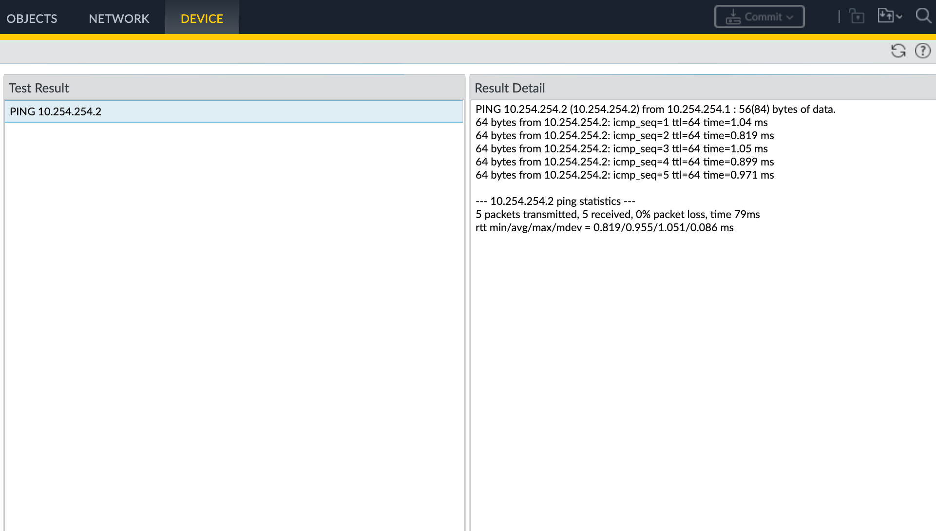
- Choose Device > Troubleshooting to test connectivity between the Palo Alto Networks MVEs.
- Select Ping from the Select Test drop-down list.
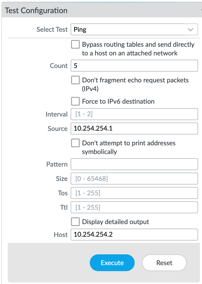
- Enter the relevant details.
See the Palo Alto Networks Tech Docs for information on these fields. - Click Execute to run the test.